


10
Electronic Neuron Models
The Nernst equation (Equation 3.21), which expresses the required membrane voltage to equilibrate the ion flux through the membrane for an existing concentration ratio of a particular ion species. Because the Nernst equation evaluates the ion moving force due to a concentration gradient as a voltage [V], this may be represented in equivalent electric circuits as a battery.
The cable model of an axon, which is composed of external and internal resistances as well as the electric properties of the membrane. This equivalent circuit may be used to calculate the general cable equation of the axon (Equation 3.45) describing the subthreshold transmembrane voltage response to a constant current stimulation. The time-varying equations describing the behavior of the transmembrane voltage due to a step-impulse stimulation are also of interest (though more complicated). Their solutions were illustrated in Figure 3.11. The equivalent circuit for (approximate) derivation of the strength-duration equation, Equation 3.58, was shown in Figure 3.12.
The equivalent electric circuits describing the behavior of the axon under conditions of nerve propagation, or under space-clamp and voltage-clamp conditions, are shown in Figures 4.1, 4.2, and 4.3; the corresponding equations are 4.1, 4.2, and 4.3, respectively.
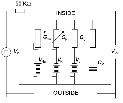
The electric circuit for the parallel-conductance model of the membrane, which contains pathways for sodium, potassium, and chloride ion currents, is illustrated in Figure 4.10, and its behavior described by Equation 4.10. This equation includes the following passive electric parameters (electronic components): membrane capacitance, Nernst voltages for sodium, potassium, and chloride ions, as well as the leakage conductance. Further, the circuit includes the behavior of the active parameters, the sodium and potassium conductances, as described by the Hodgkin-Huxley equations (Equations 4.12-4.24).
 Thus our understanding of the electric behavior of excitable tissue, and our methods to illustrate it are strongly tied to the concepts of electronic circuits and to the equations describing their behavior. From this standpoint it is possible to proceed to realize physically the electronic equivalent circuits for the excitable tissues. The physical realization of the electronic equivalent circuits of excitable tissues has two main purposes:
It provides us with an opportunity to verify that the models we have constructed really behave the same as the excitable tissue that they should model - that is, that the model is correct. If the behavior of the model is not completely correct, we may be able to adjust the properties of the model and thereby improve our understanding of the behavior of the tissue. This analysis of the behavior of the excitable tissue is one general purpose of modeling work.
There exists also the possibility of constructing, or synthesizing electronic circuits, whose behavior is similar to neural tissue, and which perform information processing in a way that also is similar to nature. In its most advanced form, it is called neural computing.
In Section 7.3 we discussed the concept of modeling in general. Various models in the neurosciences are discussed in Miller (1992). In this chapter, we discuss especially electronic neural modeling including representative examples of electronic neuron models developed to realize the electric behavior of neurons. A more comprehensive review of the electronic neuron models constructed with discrete electronic components may be found in Malmivuo (1973) and Reiss et al. (1964).
We should note that simulation of electric circuits with digital computers is another way to investigate the behavior of the electronic models. Despite this fact, electronic neural modeling is important because it is the bridge to construction of electronic circuits, which are the elements of neurocomputers.
The first computers were called "electric brains." At that time, there was a popular conception that computers could think, or that such computers would soon be available. In reality, however, even computers of today must be programmed exactly to do the desired task.
Artificial intelligence has been a popular buzzword for decades. It has produced some useful expert systems, chess-playing programs, and some limited speech and character recognition systems. These remain in the domain of carefully crafted algorithmic programs that perform a specific task. A self-programming computer does not exist. The Turing test of machine intelligence is that a machine is intelligent if in conversing with it, one is unable to tell whether one is talking to a human or a machine. By this criterion artificial intelligence does not seem any closer to realization than it was 30 years ago.
If we make an attempt to build an electronic brain, it makes sense to study how a biological brain works and then to try to imitate nature. This idea has not been ignored by scientists. Real brains, even those of primitive animals, are, however, enormously complex structures. The human brain contains about 1011 neurons, each capable of storing more than a single bit of data.
Computers are approaching the point at which they could have a comparable memory capacity. Whereas computer instruction times are measured in nanoseconds, mammalian information processing is done in milliseconds. However, this speed advantage for the computer is superseded by the massively parallel structure of the nervous system; each neuron processes information and has a large number of interconnections to other neurons. Multiprocessor computers are now being built, but making effective use of thousands of processors is a task that is still a challenge for computer theory (Tonk and Hopfield, 1987).
This chapter considers representative examples of electronic neuron models (or neuromimes) that describe the generation of the action impulse, the neuron as an independent unit, and the propagation of the nerve impulse in the axon.
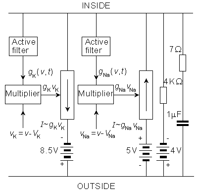
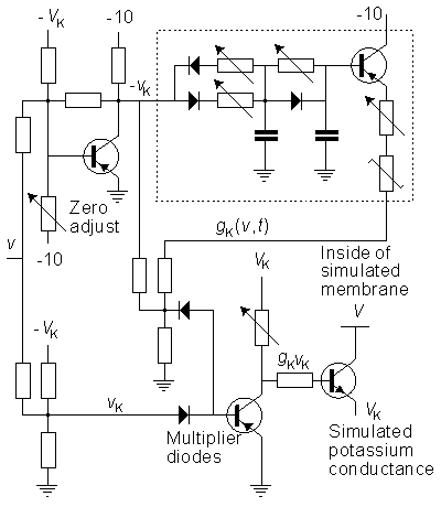
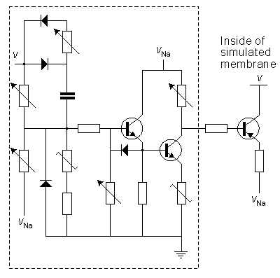
We discuss here the model published by Lewis in 1964. Lewis realized the sodium and potassium conductances using electronic hardware in the form of active filters, as shown in the block diagram of Figure 10.1. Since the output of the model is the transmembrane voltage Vm, the potassium current can be evaluated by multiplying the voltage corresponding to GK by (Vm - VK). Figure 10.1 is consequently an accurate physical analog to the Hodgkin-Huxley expressions, and the behavior of the output voltage Vm corresponds to that predicted by the Hodgkin-Huxley equations.
The electronic circuits in the Lewis neuromime had provision for inserting (and varying) not only such constants as GK max, GNa max, VK, VNa, VCl, which enter the Hodgkin-Huxley formulation, but also th, tm, tn, which allow modifications from the Hodgkin-Huxley equations. The goal of Lewis's research was to simulate the behavior of a neuronal network, including coupled neurons, each of which is simulated by a neuromime; this is documented later in this chapter.
In the electronic realization the voltages of the biological membrane are multiplied by 100 to fit the electronic circuit. In other quantities, the original values of the biological membrane have been used. In the following, the components of the model are discussed separately.
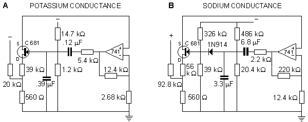
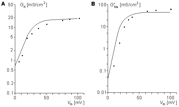
In the Roy model the conductance is controlled by a circuit including an operational amplifier, capacitors, and resistors. This circuit is designed to make the conductance behave according to the Hodgkin-Huxley model. Roy's main goal was to achieve a very simple model rather than to simulate accurately the Hodgkin-Huxley model. Nevertheless, the measurements resulting from his model, shown in Figures 10.7 and 10.8, are reasonably close to the results obtained by Hodgkin and Huxley.
Figure 10.7 illustrates the steady-state values for the potassium and sodium conductances as a function of applied voltage. Note that for potassium conductance the value given is the steady-state value, which it reaches in steady state. For sodium the illustrated value is  ; it is the value that the sodium conductance would attain if h remained at its resting level (h0). (The potassium and sodium conductance values of Hodgkin and Huxley are from tables 1 and 2, respectively, in Hodgkin and Huxley, 1952.)
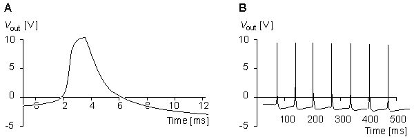
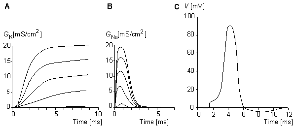
The full membrane model was obtained by connecting the potassium and sodium conductances in series with their respective batteries and simulating the membrane capacitance with a capacitor of 4.7 nF and simulating the leakage conductance with a resistance of 200 Wk . The results from the simulation of the action pulse are illustrated in Figure 10.8..
; it is the value that the sodium conductance would attain if h remained at its resting level (h0). (The potassium and sodium conductance values of Hodgkin and Huxley are from tables 1 and 2, respectively, in Hodgkin and Huxley, 1952.)
The full membrane model was obtained by connecting the potassium and sodium conductances in series with their respective batteries and simulating the membrane capacitance with a capacitor of 4.7 nF and simulating the leakage conductance with a resistance of 200 Wk . The results from the simulation of the action pulse are illustrated in Figure 10.8..
This neuron model is divided into two sections: the synaptic section and the section generating the action pulse. Both sections consist of parallel circuits connected to the nodes representing the intracellular and extracellular sites of the membrane.
The section representing the synaptic junction is divided into two components. One of these represents the inhibitory junction and the other the excitatory junction. The sensitivity of the section generating the action pulse to a stimulus introduced at the excitatory synaptic junction is reduced by the voltage introduced at the inhibitory junction. The section generating the action pulse is based on the Hodgkin-Huxley model. As described earlier, it consists of the normal circuits simulating the sodium and potassium conductances, the leakage conductance, and the membrane capacitance. The circuit also includes an amplifier for the output signal.
This neuron model which is relatively complicated, is to be used in research on neural networks. However, it is actually a simplified version of Lewis's 46-transistor network having the same form. The purpose of this simplified Lewis model is to simulate the form of the action pulse, not with the highest possible accuracy but, rather, with a sufficient accuracy provided by a simple model. Figures 10.10, 10.11, and 10.12 show the behavior of the model compared to the simulation based directly on the Hodgkin and Huxley model.
From Figure 10.10 we find that when the stimulation current begins, the sodium ion current determined by Lewis (I'Na) rises to its peak value almost immediately, whereas the sodium ion current of the Hodgkin-Huxley biological nerve (INa) rises much more slowly. The exponential decay of the current occurs at about the same speed in both. The behavior of the potassium ion current is very similar in both the model and the biological membrane as simulated by Hodgkin and Huxley.
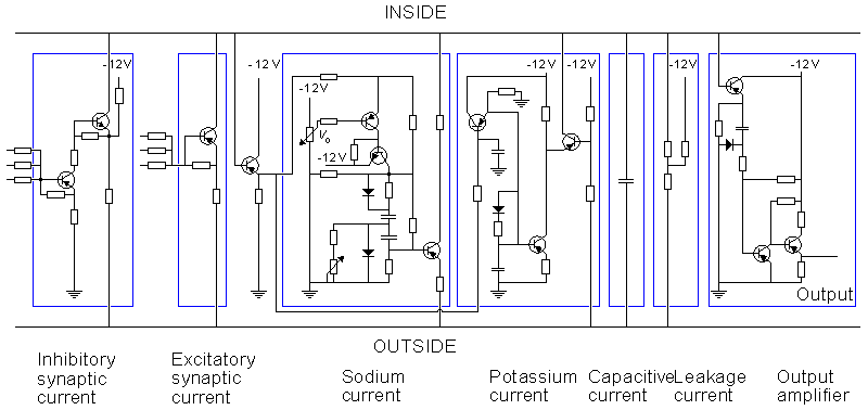
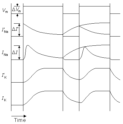
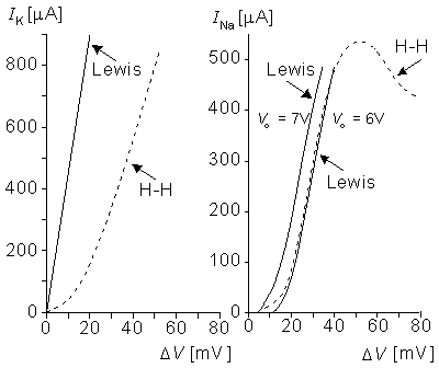
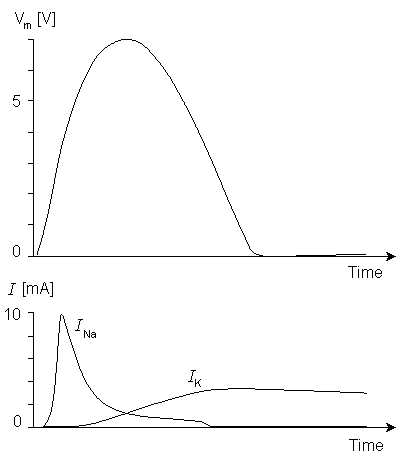
Figure 10.11A and 10.11B compare the potassium and sodium ion currents of the Lewis model to those in the Hodgkin-Huxley model, respectively. Figure 10.12 illustrates the action pulse generated by the Lewis model. The peak magnitude of the simulated sodium current is 10 mA. This magnitude is equivalent to approximately 450 µA/cm2 in the membrane, which is about half of the value calculated by Hodgkin and Huxley from their model. The maximum potassium current in the circuit is 3 mA, corresponding to 135 µA/cm2 in the membrane. The author gave no calibration for the membrane potential or for the time axis.
The electronic realizations of the Hodgkin-Huxley model are very accurate in simulating the function of a single neuron. However, when one is trying to simulate the function of neural networks, they become very complicated. Many scientists feel that when simulating large neural networks, the internal construction of its element may not be too important. It may be satisfactory simply to ensure that the elements produce an action pulse in response to the stimuli in a manner similar to an actual neuron. On this basis, Leon D. Harmon constructed a neuron model having a very simple circuit. With this model he performed experiments in which he simulated many functions characteristic of the neuron (Harmon, 1961).
The circuit of the Harmon neuron model is given in Figure 10.13. Figures 10.13A and 10.13B show the preliminary and more advanced versions of the circuit, respectively. The model is equipped with five excitatory inputs which can be adjusted. These include diode circuits representing various synaptic functions. The signal introduced at excitatory inputs charges the 0.02 µF capacitor which, after reaching a voltage of about 1.5 V, allows the monostable multivibrator, formed by transistors T1 and T2, to generate the action pulse. This impulse is amplified by transistors T3 and T4. The output of one neuron model may drive the inputs of perhaps 100 neighboring neuron models. The basic model also includes an inhibitory input. A pulse introduced at this input has the effect of decreasing the sensitivity to the excitatory inputs..
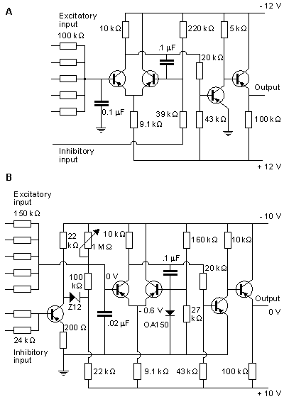
By connecting capacitors between the input and output ports of the neuron model, it is possible to realize much more complex functions. Harmon performed experiments also with combinations of many neuron models. Furthermore, Harmon investigated propagation of the action pulse by chaining models together. These neuron models can be applied to simulate quite complex neural networks, and even to model brain waves.
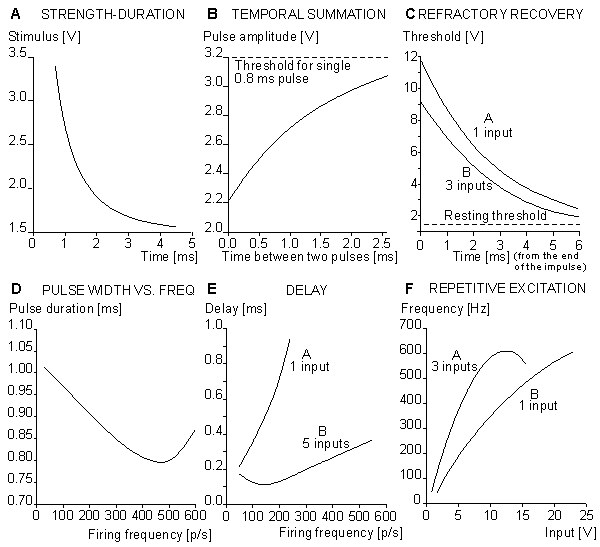
(A) strength-duration curve;
(B) temporal summation of the stimulus;
(C) refractory recovery;
(D) the output pulse width as a function of the pulse frequency;
(E) the delay between initiation of excitation and initiation of the action pulse as a function of firing frequency; and
(F) the behavior of the model in repetitive excitation. The input frequency is 700 p/s.Figures 10.16A and 10.16B illustrate the simulation of propagation of an action pulse in a model consisting of a chain of axon units, as described in Figure 10.15. Curve A represents the case with a chain of six units, and curve B a continuous ring of 10 units. In the latter, the signals are recorded from every second unit. A six-unit model represents a section of a squid axon 4 cm long and 1 mm in diameter. Figure 10.15A shows that the conduction time of the action pulse from unit three (where it has reached the final form) to unit six (i.e., three increments of distance) is 1.4 ms. Because the full six-unit model forms five increments of distance, the modeled conduction velocity was 17 m/s. This is comparable to spike conduction velocities (14 - 23 m/s) measured in squid giant axons..
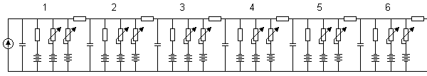
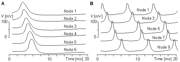
(A) a six-unit chain and
(B) a ten-unit ring.Stefan Prange (1988, 1990) has developed an electronic neuron model that is realized with integrated circuit technology. The circuit includes one neuron with eight synapses. The chip area of the integrated circuit is 4.5 × 5 mm2. The array contains about 200 NPN and 100 PNP transistors, and about 200 of them are used. The circuit is fabricated with one metal layer with a line width of 12 µm. Because the model is realized with integrated circuit technology, it is easy to produce in large quantities, which is necessary for simulating neural networks. These experiments, however, have not yet been made with this model.
In 1991, Misha Mahowald and Rodney Douglas published an integrated circuit realization of electronic neuron model (Mahowald and Douglas, 1991). It was realized with complementary metal oxide semiconductor (CMOS) circuits using very large-scale integrated (VLSI) technology. Their model simulates very accurately the spikes of a neocortical neuron. The power dissipation of the circuit is 60 µW, and it occupies less than 0.1 mm2. The authors estimate that 100-200 such neurons could be fabricated on a 1 cm × 1 cm die.
Eccles JC (1964): The Physiology of Synapses, 316 pp. Springer-Verlag, Berlin.
Harmon LD (1961): Studies with artificial neurons, I: Properties and functions of an artificial neuron. Kybernetik Heft 3(Dez.): 89-101.
Hecht-Nielsen R (1988): Neurocomputing: Picking the human brain. IEEE Spectrum 25:(3(March)) 36-41.
Hodgkin AL, Huxley AF (1952): A quantitative description of membrane current and its application to conduction and excitation in nerve. J. Physiol. (Lond.) 117: 500-44.
Lewis ER (1964): An electronic model of the neuron based on the dynamics of potassium and sodium ion fluxes. In Neural Theory and Modelling. Proceedings of the 1962 Ojai Symposium, ed. RF Reiss, HJ Hamilton, LD Harmon, G Hoyle, D Kennedy, O Schmitt, CAG Wiersma, p. 427, Stanford University Press, Stanford.
Lewis ER (1968): Using electronic circuits to model simple neuroelectric interactions. Proc. IEEE 56:(6) 931-49. (Special issue on studies of neural elements and systems).
Mahowald MA, Douglas RJ (1991): A silicon neuron. Nature 354:(December) 515-8.
Mahowald MA, Douglas RJ, LeMoncheck JE, Mead CA (1992): An introduction to silicon neural analogs. Semin. Neurosci. 4: 83-92.
Malmivuo JA (1973): Bioelectric Function of a Neuron and Its Description With Electronic Models, 195 pp. Helsinki Univ. Techn., Dept. El. Eng. (In Finnish)
Prange S (1988): Aufbau eines Neuronenmodells mit hilfe einer analogen, kundenspezifischen Schaltung. Institute of Microelectronics, Techn. Univ. Berlin, Berlin, pp. 87. (Diploma thesis)
Prange S (1990): Emulation of biology-oriented neural networks. In Proc. Int. Conf. On Parallel Processing in Neural Systems and Computers (ICNC), ed. M Eckmiller, Düsseldorf.
Roy G (1972): A simple electronic analog of the squid axon membrane: The neurofet. IEEE Trans. Biomed. Eng. BME-19:(1) 60-3.
Tonk DW, Hopfield JJ (1987): Collective computation in neuronlike circuits. Sci. Am. 257:(6) 62-70.
REFERENCES, BOOKS
Aleksander I (ed.) (1989): Neural Computing Architectures, The Design of Brain-Like Machines, 401 pp. The MIT Press, Cambridge, Mass.
Andersson JA, Rosenfeld E (eds.) (1988): Neurocomputing: Foundations of Research, 729 pp. MIT Press, Cambridge, Mass.
Grossberg S (ed.) (1988): Neural Networks and Natural Intelligence, 637 pp. MIT Press, Cambridge, Mass.
Hecht-Nielsen R (1990): Neurocomputing, 432 pp. Addison-Wesley Publishing, Reading, Mass.
MacGregor RJ (1987): Neural and Brain Modelling, 643 pp. Academic Press, San Diego.
MacGregor RJ, Lewis ER (1977): Neural Modelling: Electric Signal Processing in the Nervous System, 414 pp. Plenum Press, New York.
Miller KD (1992): The Use of Models in the Neurosciences. Semin. Neurosci. 4:(1) 92. (Special issue).
Reiss RF, Hamilton HJ, Harmon LD, Hoyle G, Kennedy D, Schmitt O, Wiersma CAG (eds.) (1964): Neural Theory and Modelling. Proceedings of the 1962 Ojai Symposium, 427 pp. Stanford University Press, Stanford.
Sejnowski T (ed.) (1989): Neural Computation, MIT Press, Cambridge, Mass.