12
Theory of Biomagnetic Measurements
 i (volume source)
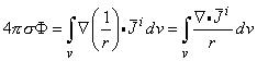
The current density throughout a volume conductor gives rise to a magnetic field given by the following relationship (Stratton, 1941; Jackson, 1975):
 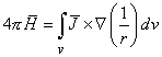 | (12.01) |
where r is the distance from an external field point at which  is evaluated to an element of volume dv inside the body, dv is a source element, and
  is an operator with respect to the source coordinates. Substituting Equation 7.2, which is repeated here,
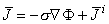 | (7.02) |
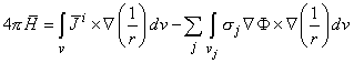
into Equation 12.1 and dividing the inhomogeneous volume conductor into homogeneous regions vj with conductivity sj, we obtain
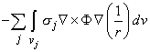
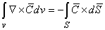
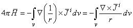
where the surface integral is taken over the surface S bounding the volume v of the volume integral. By applying 12.4 to Equation 12.3, the last term in Equation 12.2, including its sign, can now be replaced by
Finally, applying this result to Equation 12.2 and denoting again the primed and double-primed regions of conductivity to be inside and outside a boundary, respectively, and orienting d
Using the vector identity
Applying the divergence theorem to the first term on the right-hand side and using a vector expansion (i.e.,
Since
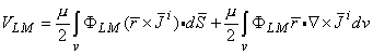
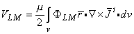
This equation corresponds to Equation 11.50 in electric measurements. The quantity FLM is the magnetic scalar potential in the volume conductor due to the reciprocal energization of the pickup lead. The expression
In Equation 12.16 this is the strength of the magnetic field source.
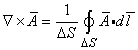
and the line integral is taken around DS at any point in the region of interest such that it is oriented in the field to maximize the integral (which designates the direction of the curl).
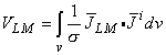
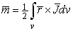
The magnetic dipole moment of a volume current distribution
where
is consequently
We now apply Equation 12.4 to 12.21 and note that the volume and hence surface integrals must be calculated in a piecewise manner for each region where s takes on a different value. Summing these integrals and designating the value of conductivity s with primed and double-primed symbols for the inside and outside of each boundary, we finally obtain from Equation 12.20:
This equation gives the magnetic dipole moment of a volume source
This section develops the form of the lead field for a detector that detects the equivalent magnetic dipole moment of a distributed volume source located in an infinite (or spherical) homogeneous volume conductor. We first have to choose the origin; we select this at the center of the source. (The selection of the origin is necessary, because of the factor r in the equation of the magnetic dipole moment, Equation 12.22.)
Substituting Equation 12.23 into Equation 12.24 gives the desired relationship between the lead voltage and magnetic dipole moment density, namely
This equation may be expressed in words as follows:
One component of the magnetic dipole moment of a volume source is obtained with a detector which, when energized, produces a homogeneous reciprocal magnetic field This reciprocal magnetic field produces a reciprocal electric field Three such identical mutually perpendicular lead fields form the three orthogonal components of a complete lead system detecting the magnetic dipole moment of a volume source.
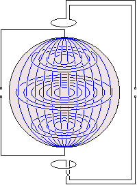
Fig. 12.4. The principle of a lead system detecting the magnetic dipole moment of a volume source.
As in the case of the detection of the electric dipole moment of a volume source, Section 11.6.9, both unipolar and bipolar leads may be used in synthesizing the ideal lead field for detecting the magnetic dipole moment of a volume source. In the case of an infinite conducting medium and a uniform reciprocal magnetic field, the lead field current flows concentrically about the symmetry axis, as shown in Figure 12.3. Then no alteration results if the conducting medium is terminated by a spherical boundary (since the lead current flow lines lie tangential to the surface). The spherical surface ensures lead current flow lines, as occurs in an infinite homogeneous medium, when a uniform reciprocal magnetic field is established along any x-, y-, and z-coordinate direction.
Fig. 12.7. Flux tubes of the reciprocal magnetic field of
In summary, we note the following details from the lead fields of ideal bipolar lead systems for detecting the electric and magnetic dipole moments of a volume source:
The lead system consists of three components.
For a spherically symmetric volume conductor, each is formed by a pair of electrodes (or electrode matrices), whose axis is in the direction of the coordinate axes. Each electrode is on opposite sides of the source, as shown in Figure 11.24.
For each of these components, when energized reciprocally, a homogeneous and linear electric field is established in the region of the volume source (see Figure 11.25). Each of these reciprocal electric fields forms a similar current field, which is called the electric lead field The lead system consists of three components.
In the spherically symmetric case, each of them is formed by a pair of magnetometers (or gradiometers) located in the direction of the coordinate axes on opposite sides of the source, as illustrated in Figure 12.6C (or 12.8).
For each of these components, when energized reciprocally, a homogeneous and linear magnetic field is established in the region of the volume source, as shown in Figure 12.4.
Each of these reciprocal magnetic fields forms an electric field, necessarily tangential to the boundaries. These reciprocal electric fields give rise to a similar electric current field, which is called the magnetic lead field
Superimposing Figures 12.8, 12.4, and 12.5 allows one more easily to visualize the generation and shape of the lead fields of magnetic leads.
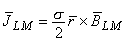
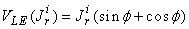
whereas for the tangential component Jit it is:
In these expressions the component lead fields are assumed uniform and of unit magnitude.
The special properties of electric lead fields, listed in Section 11.6.10, also hold for magnetic lead fields. Magnetic lead fields also have some additional special properties which can be summarized as follows:
If the volume conductor is cut or the boundary of an inhomogeneity is inserted along a lead field current flow line, the form of the lead field does not change (Malmivuo, 1976). This explains why with either a cylindrically or spherically symmetric volume conductor, the form of the symmetric magnetic lead field is unaffected. There are two important practical consequences:
Because the heart may be approximated as a sphere, the highly conducting intracardiac blood mass, which may be considered spherical and concentric, does not change the form of the lead field. This means that the Brody effect does not exist in magnetocardiography (see Chapter 18).
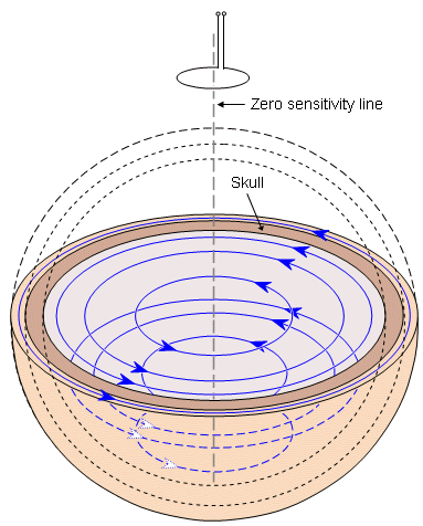
The poorly conducting skull does not affect the magnetic detection of brain activity as it does with electric detection (see Figure 12.10).
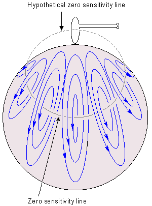
Magnetic lead fields in volume conductors exhibiting spherical symmetry are always directed tangentially. This means that the sensitivity of such magnetic leads in a spherical conductor to radial electric dipoles is always zero. This fact has special importance in the MEG (see Figure 12.11).
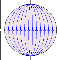
If the electrodes of a symmetric bipolar electric lead are located on the symmetry axis of the bipolar magnetic field detector arranged for a spherical volume conductor, the lead fields of these electric and magnetic leads are normal to each other throughout the volume conductor, as illustrated in Figure 12.12 (Malmivuo, 1980). (The same holds for corresponding unipolar leads as well, though not shown in the figure.)
The lead fields of all magnetic leads include at least one zero sensitivity line, where the sensitivity to electric dipoles is zero. This line exists in all volume conductors, unless there is a hole in the conductor in this region (Eskola, 1979, 1983; Eskola and Malmivuo, 1983). The zero sensitivity line itself is one tool in understanding the form of magnetic leads (as demonstrated in Figure 12.13).
The reciprocity theorem also applies to the reciprocal situation. This means that in a tank model it is possible to feed a "reciprocally reciprocal" current to the dipole in the conductor and to measure the signal from the lead. However, the result may be interpreted as having been obtained by feeding the reciprocal current to the lead with the signal measured from the dipole. The benefit of this "reciprocally reciprocal" arrangement is that for technical reasons the signal-to-noise ratio may be improved while we still have the benefit of interpreting the result as the distribution of the lead field current in the volume conductor (Malmivuo, 1976)..
Fig. 12.10. The poorly conducting skull does not affect the magnetic detection of the electric activity of the brain.
Fig. 12.11. Magnetic lead fields in volume conductors exhibiting spherical symmetry are always directed tangentially. The figure illustrates also the approximate form of the zero sensitivity line in the volume conductor. (The zero sensitivity line may be imagined to continue hypothetically through the magnetometer coil.).
Fig. 12.12. If the electrodes of a symmetric bipolar electric lead are located on the symmetry axis of the bipolar magnetic field detector arranged for a spherical volume conductor, these lead fields of the electric and magnetic leads are normal to each other throughout the volume conductor.
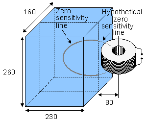
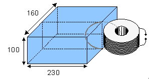
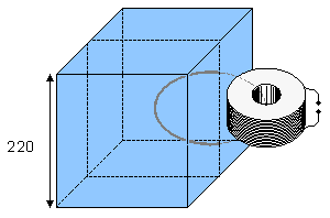
Fig. 12.13. Zero sensitivity lines in volume conductors of various forms. The dimensions are given in millimeters (Eskola, 1979, 1983; Eskola and Malmivuo, 1983). As in Figure 12.11, the zero sensitivity lines are illustrated to continue hypothetically through the magnetometer coils.
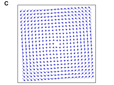
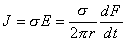
where F and V denote flow and vortex, respectively. By definition, these vector fields satisfy
and for the magnetic field:
where F =
where s is the conductivity of the medium. The current density is tangentially oriented. Now the problem reduces to the determination of the magnetic flux linking a circular loop in the medium due to a reciprocally energizing current in the coaxially situated magnetometer coil..
Fig. 12.14. Geometry for calculating the spatial sensitivity of a magnetometer in a cylindrically symmetric situation.
The basic equation for calculating the vector potential at point P due to a current I flowing in a thin conductor is
This equation can be used to calculate the vector potential at the point P in Figure 12.14. From symmetry we know that in spherical coordinates the magnitude of
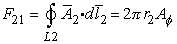
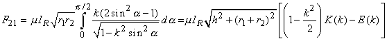
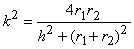
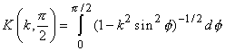
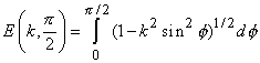
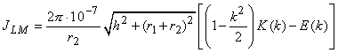
The magnetic flux F21 may be calculated from the vector potential:
where
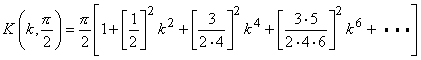
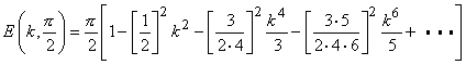
and K(k) and E(k) are complete elliptic integrals of the first and second kind, respectively. These are calculated from equations 12.38A,B. (Abramowitz and Stegun, 1964, p. 590)
The values K(k) and E(k) can also be calculated using the series:
The calculation of K(k) and E(k) is faster from the series, but they give inaccurate results at small distances from the coil and therefore the use of the Equations 12.38A,B is recommended.
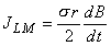
and we obtain the equation for calculating the lead field current density for a single-coil magnetometer in an infinite homogeneous volume conductor:
where all distances are measured in meters, and current density in [A/m2].
The magnetic induction may be calculated in this situation as for a dipole source. Equation 12.43 shows clearly that in the region of constant magnetic induction and constant conductivity, the lead field current density is proportional to the radial distance from the symmetry axis. Note that this equation is consistent with Equation 12.11.
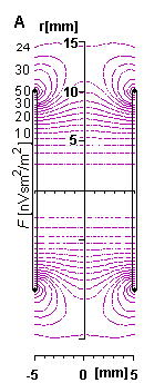
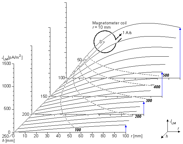
Fig. 12.15. The lead field current density distribution of a unipolar single-coil magnetometer with a 10 mm coil radius in a cylindrically symmetric volume conductor calculated from Equation 12.42. The dashed lines are the isosensitivity lines, joining the points where the lead field current density is 100, 200, 300, 400, and 500 pA/m2, respectively, as indicated by the numbers in italics.
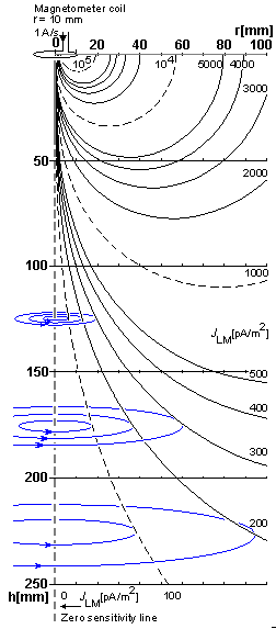
Figure 12.16 illustrates the isosensitivity lines for a unipolar single-coil magnetometer of Figure 12.15; the coil radius is 10 mm, and the volume conductor is cylindrically symmetric. The vertical axis indicates the distance h from the magnetometer and the horizontal axis the radial distance r from the symmetry axis. The symmetry axis, drawn with thick dashed line, is the zero sensitivity line. The lead field current flow lines are concentric circles around the symmetry axis. To illustrate this, the figure shows three flow lines representing the current densities 100, 200, and 300 pA/m2 at the levels h = 125 mm, 175 mm and 225 mm. As in the previous figure, the lead field current density values are calculated for a reciprocal current of IR = 1 A/s.
Fig. 12.16. The isosensitivity lines for a unipolar single-coil magnetometer of Figure 12.15; the coil radius is 10 mm, and the volume conductor is cylindrically symmetric. The vertical axis indicates the distance h from the magnetometer and the horizontal axis the radial distance r from the symmetry axis. The symmetry axis, drawn with a thick dashed line, is the zero sensitivity line. Thin solid lines represent lead field current flow lines.
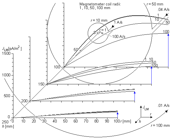
Fig. 12.17. Lead field current density for unipolar leads of coils with 1 mm, 10 mm, 50 mm, and 100 mm radii. The energizing current in the coils is normalized in relation to the coil area to obtain a constant dipole moment.
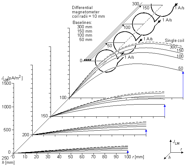
Fig. 12.18. Lead field current density for unipolar leads realized with differential magnetometers of 10 mm coil radius and with 300 mm, 150 mm, 100 mm, and 50 mm baseline.
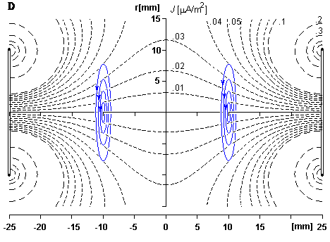
Fig. 12.19. The lead field current density distribution of a bipolar lead in a cylindrically symmetric volume conductor realized with two coaxial single-coil magnetometers with 10 mm coil radius. The distance between the coils is 340 mm. The dashed lines are the isosensitivity lines, joining the points where the lead field current density is 500 and 1000 pA/m2, respectively, as indicated with the numbers in italics.
Fig. 12.20. The isosensitivity lines for the bipolar lead of Figure 12.19. The coil radii are 10 mm and the distance between the coils is 340 mm. The vertical axis indicates the distance h from the first magnetometer and the horizontal axis the radial distance r from the symmetry axis. The symmetry axis, drawn with thick dashed line, is the zero sensitivity line. Lead field current flow lines encircle the symmetry axis and are illustrated with thin solid lines.
Abramowitz M, Stegun IA (eds.) (1964): Handbook of Mathematical Functions With Formulas, Graphs, and Mathematical Tables, 1046 pp. Wiley, New York, N.Y.
Baule GM, McFee R (1963): Detection of the magnetic field of the heart. Am. Heart J. 55:(7) 95-6.
Eskola H (1979): Properties of the unipositional lead system in the measurement of the vector magnetocardiogram. Tampere Univ. Tech., Tampere, Finland, pp. 72. (In Finnish) (Master's thesis)
Eskola H (1983): On the properties of vector magnetocardiographic leads. Tampere Univ. Tech., Tampere, Finland, Thesis, pp. 154. (Dr. tech. thesis)
Eskola HJ, Malmivuo JA (1983): Optimizing vector magnetocardiographic lead fields by using physical torso model. Il Nuovo Cim. 2:(2) 356-67.
Estola K-P, Malmivuo JA (1982): Air-Core induction coil magnetometer design. J. Phys. E.: Sci. Instrum. 15: 1110-3.
Faraday M (1834): Experimental researches on electricity, 7th series. Phil. Trans. R. Soc. (Lond.) 124: 77-122.
Geselowitz DB (1970): On the magnetic field generated outside an inhomogeneous volume conductor by internal current sources. IEEE Trans. Magn. MAG-6:(2) 346-7.
Jackson JD (1975): Classical Electrodynamics, 2nd ed., 84 pp. John Wiley, New York.
Malmivuo JA (1976): On the detection of the magnetic heart vector - An application of the reciprocity theorem. Helsinki Univ. Tech., Acta Polytechn. Scand., El. Eng. Series. Vol. 39., pp. 112. (Dr. tech. thesis)
Malmivuo JA (1980): Distribution of MEG detector sensitivity: An application of reciprocity. Med. & Biol. Eng. & Comput. 18:(3) 365-70.
Malmivuo JA, Lekkala JO, Kontro P, Suomaa L, Vihinen H (1987): Improvement of the properties of an eddy current magnetic shield with active compensation. J. Phys. E.: Sci. Instrum. 20:(1) 151-64.
Morse PM, Feshbach H (1953): Methods of Theoretical Physics. Part I, 997 pp. McGraw-Hill, New York.
Plonsey R (1972): Capability and limitations of electrocardiography and magnetocardiography. IEEE Trans. Biomed. Eng. BME-19:(3) 239-44.
Plonsey R (1982): The nature of sources of bioelectric and biomagnetic fields. Biophys. J. 39: 309-19.
Plonsey R, Collin R (1961): Principles and Applications of Electromagnetic Fields, 554 pp. McGraw-Hill, New York.
Rush S (1975): On the interdependence of magnetic and electric body surface recordings. IEEE Trans. Biomed. Eng. BME-22: 157-67.
Smythe WR (1968): Static and Dynamic Electricity, 3rd ed., 623 pp. McGraw-Hill, New York.
Stratton JA (1941): Electromagnetic Theory, McGraw-Hill, New York.
Williamson SJ, Romani G-L, Kaufman L, Modena I (eds.) (1983): Biomagnetism: An Interdisciplinary Approach. NATO ASI Series, Series A: Life Sciences, Vol. 66, 706 pp. Plenum Press, New York.
(12.02)  If the vector identity
  F
F  = F + F is used, then the integrand of the last term in Equation 12.2 can be written sj [F (1/r)] - F (1/r). Since F = 0 for any F, we may replace the last term including its sign by
(12.03) We now make use of the following vector identity (Stratton, 1941, p. 604):
(12.04)
(12.05)  j from the primed to double-primed region, we obtain (note that each interface arises twice, once as the surface of vj and secondly from surfaces of each neighboring region of vj )
(12.06) This equation describes the magnetic field outside a finite volume conductor containing internal (electric) volume sources i and inhomogeneities (s"j - s'j ). It was first derived by David Geselowitz (Geselowitz, 1970).
It is important to notice that the first term on the right-hand side of Equation 12.6, involving i, represents the contribution of the volume source, and the second term the effect of the boundaries and inhomogeneities. The impressed source i arises from cellular activity and hence has diagnostic value whereas the second term can be considered a distortion due to the inhomogeneities of the volume conductor. These very same sources were identified earlier when the electric field generated by them was being evaluated (see Equation 7.10). (Just, as in the electric case, these terms are also referred to as primary source and secondary source.)
Similarly, as discussed in connection with Equation 7.10, it is easy to recognize that if the volume conductor is homogeneous, the differences (s"j - s'j ) in the second expression are zero, and it drops out. Then the equation reduces to the equation of the magnetic field due to the distribution of a volume source in a homogeneous volume conductor. This is introduced later as Equation 12.20. In the design of high-quality biomagnetic instrumentation, the goal is to cancel the effect of the secondary sources to the extent possible.
From an examination of Equation 12.6 one can conclude that the discontinuity in conductivity is equivalent to a secondary surface source  j given by j = (s"j - s'j )F
 where F is the surface potential on Sj. Note that j is the same secondary current source for electric fields (note Equation 7.10) as for magnetic fields.
12.2 NATURE OF THE BIOMAGNETIC SOURCES
Equation 12.6 shows that the physiological phenomenon that is the source of the biomagnetic signal is the electric activity of the tissue i (described earlier). Thus, for instance, the source for the magnetocardiogram (MCG) or magnetoencephalogram (MEG) is the electric activity of the cardiac muscle or nerve cells, respectively, as it is the source of the electrocardiogram (ECG) and electroencephalogram (EEG). The theoretical difference between biomagnetic and bioelectric signals is the difference in the sensitivity distribution of these measurements. The sensitivity distribution (the form of the lead field) of electric measurements was discussed in detail in the previous chapter. The sensitivity distribution of magnetic measurements is discussed in detail in this chapter. (The technical distinctions in the electric and magnetic detectors introduce additional differences. These are briefly discussed later in connection with magnetocardiography in Chapter 20.)
The difference between biomagnetic and bioelectric signals may be also seen from the form of their mathematical equations. When comparing the Equations 12.6 and 7.10, one can note that the magnetic field arises from the curl and the electric field from the divergence of the source. This distinction holds both for the first component on the right-hand side of these equations arising from the distribution of impressed current, and for the second component arising from the boundaries of the inhomogeneities of the volume source.
It is pointed out that in the design of magnetic leads one must keep in mind the electric origin of the magnetic signal and the characteristic form of the sensitivity distribution of the magnetic measurement. If the lead of a magnetic measurement is not carefully designed, it is possible that the sensitivity distribution of a magnetic lead will be similar to that of another electric lead. In such a case the magnetic measurement does not provide any new information about the source.
Please note that the biomagnetic signal discussed above is assumed not to arise from magnetic material because such material does not exist in these tissues. There are special circumstances, however, where biomagnetic fields are produced by magnetic materials - for example, in the case of the signal due to the magnetic material contaminating the lungs of welders or the iron accumulating in the liver in certain diseases. Such fields are not discussed in this textbook.
Biomagnetic fields have very low amplitude compared to the ambient noise fields and to the sensitivity of the detectors. A summary of these fields is presented in Figure 12.1 (Malmivuo et al., 1987). The figure indicates that it is possible to detect the MCG with induction coil magnetometers, albeit with a reasonably poor signal-to-noise ratio. However, even the most sensitive induction coil magnetometer built for biomagnetic purposes (Estola and Malmivuo, 1982) is not sensitive enough to detect the MEG for clinical use. Therefore, the Superconducting QUantum Interference Device (SQUID) is the only instrument that is sensitive enough for high-quality biomagnetic measurements. The instrumentation for measuring biomagnetic fields is not discussed further in this textbook. A good overview of the instrumentation is published by Williamson et al. (1983)..
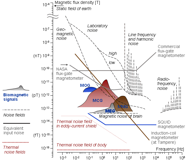
Fig. 12.1. Magnetic signals produced by various sources.
Biomagnetic signals: MCG = magnetocardiogram, MMG = magnetomyogram, MEG = magnetoencephalogram, MOG = magneto-oculogram
Noise fields: static field of the Earth, geomagnetic fluctuations, laboratory noise, line frequency noise, radio frequency noise
Equivalent input noise: commercial flux-gate magnetometer, ring-core flux-gate (NASA), induction coil magnetometer, SQUID-magnetometer.
Thermal noise fields: eddy current shield, the human body.12.3 RECIPROCITY THEOREM FOR MAGNETIC FIELDS
PRECONDITIONS:
SOURCE: Distribution of impressed current source elements i (volume source)
CONDUCTOR: Infinite, homogeneous; or finite, inhomogeneous with cylindrical symmetry
12.3.1 The Form of the Magnetic Lead Field
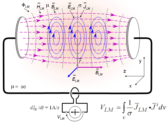
Plonsey extended the application of the reciprocity theorem to the time-varying conditions that arise in biomagnetic measurements (Plonsey, 1972). That development follows along lines similar to the proof of the reciprocity theorem for electric fields and therefore need not be repeated here. Only the equations for the reciprocity theorem for magnetic measurements are derived here. In this discussion subscript L denotes "lead," as in the previous chapter, but we add a subscript M to denote "magnetic leads" due to reciprocal current of unit time derivative.
The current induced in a conductor depends on the rate of change of the magnetic flux that links the current loop. In analogy to the electric field case (see Equations 11.30 and 11.52), the reciprocally energizing (time-varying) current Ir is normalized so that its time derivative is unity for all values of w. The necessary equations for the lead field theory for biomagnetic measurements can then be readily obtained from the corresponding equations in electric measurements.
An elementary bipolar lead in magnetic measurements is a solenoid (coil) with a core and disklike terminals of infinite permeability, as illustrated in Figure 12.2. If the coil is energized with a current, a magnetic field is set up, which can be considered to result from magnetic charges (equal and opposite) at the terminals of the core. These terminals are called magnodes (Baule and McFee, 1963). (The word "electrode" was introduced by Michael Faraday (1834).) This elementary bipolar magnetic lead is equivalent to the elementary bipolar electric lead illustrated in Figure 11.23.
When a reciprocal current Ir is fed to the elementary magnetic lead, it produces in an infinite space of uniform permeability a reciprocal magnetic scalar potential field FLM of the same spatial behavior as the reciprocal scalar electric potential field FLE in an infinite medium of uniform conductivity arising from a reciprocally energized electric lead, whose electrodes are located at sites corresponding to the magnodes. As noted in Section 11.6.6, if the electrodes or magnodes are parallel and their dimensions are large compared to their separation, both FLE and FLM are uniform in the central region..
(12.13)  (FLM
(FLM i ) = FLM (i ) + FLM(i ), we obtain from Equation 12.13

(12.14) (i ) = i - i ) on the second term of Equation 12.14, and noting that = 0, we obtain
(12.15) i = 0 at the boundary of the medium, the surface integral equals zero, and we may write
(12.16) i is defined as the vortex source,  v :
v :
v = i(12.17) The designation of vortex to this source arises out of the definition of curl. The latter is the circulation per unit area, that is:
(12.18) If one considers the velocity field associated with a volume of water in a container, then its flow source must be zero if water is neither added nor withdrawn. But the field is not necessarily zero in the absence of flow source because the water can be stirred up, thereby creating a nonzero field. But the vortex thus created leads to a nonzero curl since there obviously exists a circulation. This explains the use of the term "vortex" as well as its important role as the source of a field independent of the flow source.
12.3.3 Summary of the Lead Field Theoretical Equations for Electric and Magnetic Measurements
As summarized in Figure 12.2, as a consequence of the reciprocal energization of a magnetic lead, the following five reciprocal fields are created in the volume conductor: magnetic scalar potential field FLM (illustrated with isopotential surfaces), magnetic field LM (illustrated with field lines), magnetic induction  LM (illustrated with flux lines), electric field
  LM (illustrated with field lines), and current field LM (illustrated with current flow lines and called the lead field).
In addition to these five fields we may define for a magnetic lead a sixth field: the field of isosensitivity surfaces. This is a similar concept as was defined for an electric lead in Section 11.6.6. When the magnetic permeability is isotropic (as it usually is in biological tissues), the magnetic field lines coincide with the magnetic induction flux lines. When the conductivity is isotropic, the electric field lines coincide with the current flow lines. Thus in summary, in a lead system detecting the magnetic dipole moment of a volume source (see Section 12.6) from the aforementioned six fields, the magnetic field lines coincide with the magnetic flux lines and the electric field lines coincide with the lead field flow lines. Similarly as in the electric case (see Section 11.6.6), the magnetic scalar isopotential surfaces coincide with the magnetic isofield and isoflux surfaces.
Table 12.1 summarizes the lead field theoretical equations for electric and magnetic measurements.
The spatial dependence of the electric and magnetic scalar potentials FLE and FLM, are found from Laplace's equation. These fields will have the same form (as will LE vs. LM), if the shape and location of the electrodes and magnodes are similar and if there is no effect of the volume conductor inhomogeneities or boundary with air. Similarly, the equations for the electric and magnetic signals VLE and VLM, as integrals of the scalar product (dot product) of the lead field and the impressed current density field, have the same form.
The difference in the sensitivity distributions of the electric and magnetic detection of the impressed current density i is a result of the difference in the form of the electric and magnetic lead fields LE and LM. The first has the form of the reciprocal electric field, whereas the latter has the form of the curl of the reciprocal magnetic field.
We emphasize again that this discussion of the magnetic field is restricted to the case of axially symmetric and uniform conditions (which are expected to be applicable as a good approximation in many applications).
LM (illustrated with field lines), and current field LM (illustrated with current flow lines and called the lead field).
In addition to these five fields we may define for a magnetic lead a sixth field: the field of isosensitivity surfaces. This is a similar concept as was defined for an electric lead in Section 11.6.6. When the magnetic permeability is isotropic (as it usually is in biological tissues), the magnetic field lines coincide with the magnetic induction flux lines. When the conductivity is isotropic, the electric field lines coincide with the current flow lines. Thus in summary, in a lead system detecting the magnetic dipole moment of a volume source (see Section 12.6) from the aforementioned six fields, the magnetic field lines coincide with the magnetic flux lines and the electric field lines coincide with the lead field flow lines. Similarly as in the electric case (see Section 11.6.6), the magnetic scalar isopotential surfaces coincide with the magnetic isofield and isoflux surfaces.
Table 12.1 summarizes the lead field theoretical equations for electric and magnetic measurements.
The spatial dependence of the electric and magnetic scalar potentials FLE and FLM, are found from Laplace's equation. These fields will have the same form (as will LE vs. LM), if the shape and location of the electrodes and magnodes are similar and if there is no effect of the volume conductor inhomogeneities or boundary with air. Similarly, the equations for the electric and magnetic signals VLE and VLM, as integrals of the scalar product (dot product) of the lead field and the impressed current density field, have the same form.
The difference in the sensitivity distributions of the electric and magnetic detection of the impressed current density i is a result of the difference in the form of the electric and magnetic lead fields LE and LM. The first has the form of the reciprocal electric field, whereas the latter has the form of the curl of the reciprocal magnetic field.
We emphasize again that this discussion of the magnetic field is restricted to the case of axially symmetric and uniform conditions (which are expected to be applicable as a good approximation in many applications).
Table 12.1. The equations for electric and magnetic leads
Quantity
Electric lead
Magnetic lead
Field as a negative gradient
of the scalar potential
of the reciprocal energizationLE = - FLE (11.53) LM = - FLM (12.7)
Magnetic induction
due to reciprocal energization
LM = mLM (12.8)
Reciprocal electric field *)
LE( = - FLE) (11.53)
LM = �LM (12.9)
Lead field (current field)
LE = sLE (11.54)
LM = sLM (12.10)
Detected signal when:
IRE = 1 A,
dIRM/dt = 1 A/s 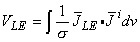
(11.30)
(12.12)
*) Note: The essential difference between the electric and magnetic lead fields is explained as follows: The reciprocal electric field of the electric lead has the form of the negative gradient of the electric scalar potential (as explained on the first line of this table). The reciprocal electric field of the magnetic lead has the form of the curl of the negative gradient of the magnetic scalar potential. (In both cases, the lead field, which is defined as the current field, is obtained from the reciprocal electric field by multiplying by the conductivity.) Numbers in parentheses refer to equation numbers in text. 12.4 THE MAGNETIC DIPOLE MOMENT OF A VOLUME SOURCE
PRECONDITIONS:
SOURCE: Distribution of i forming a volume source
CONDUCTOR: Finite, inhomogeneous
with respect to an arbitrary origin is defined as (Stratton, 1941):
(12.19) is a radius vector from the origin. The magnetic dipole moment of the total current density , which includes a distributed volume current source i and its conduction current,
= i - sF(7.2)
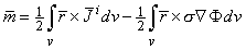
(12.20) Assuming s to be piecewise constant, we may use the vector identity F = F + F = -F (because = 0), and convert the second term on the right-hand side of Equation 12.20 to the form:
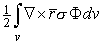
(12.21)
(12.22) i located in a finite inhomogeneous volume conductor. As in Equation 12.6, the first term on the right-hand side of Equation 12.22 represents the contribution of the volume source, and the second term the contribution of the boundaries between regions of different conductivity. This equation was first derived by David Geselowitz (Geselowitz, 1970).
12.5 IDEAL LEAD FIELD OF A LEAD DETECTING THE EQUIVALENT MAGNETIC DIPOLE OF A VOLUME SOURCE
PRECONDITIONS:
SOURCE: Distribution of i forming volume source (at the origin)
CONDUCTOR: Infinite (or spherical) homogeneous
The total magnetic dipole moment of a volume source is evaluated in Equation 12.20 as a volume integral. We notice from this equation that a magnetic dipole moment density function is given by the integrand, namely

(12.23) Equation 12.14 provides a relationship between the (magnetic) lead voltage and the current source distribution i, namely

(12.24)
(12.25)
LM in the negative direction of the coordinate axis in the region of the volume source.
LM = �LM and a magnetic lead field LM = sLM in the direction tangential to the symmetry axis.
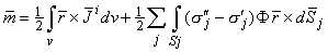
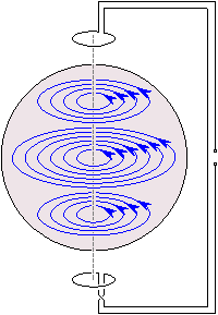
Figure 12.4 presents the principle of a lead system detecting the magnetic dipole moment of a volume source. It consists of a bipolar coil system (Figure 12.4A) which produces in its center the three components of the reciprocal magnetic field LM (Figure 12.4B). Note, that the region where the coils of Figure 12.4A produce linear reciprocal magnetic fields is rather small, as will be explained later, and therefore the Figures 12.4A and 12.4B are not in scale. The three reciprocal magnetic fields LM produce the three components of the reciprocal electric field LM and the lead field LM that are illustrated in Figure 12.5. It is important to note that the reciprocal magnetic field LM has the same geometrical form as the reciprocal electric field LE of a detector which detects the electric dipole moment of a volume source, Figure 11.24.
Similarly as in the equation of the electric field of a volume source, Equation 7.9, the second term on the right-hand side of Equation 12.22 represents the contribution of the boundaries and inhomogeneities to the magnetic dipole moment. This is equivalent to the effect of the boundaries and inhomogeneities on the form of the lead field. In general, a detector that produces an ideal lead field in the source region despite the boundaries and inhomogeneities of the volume conductor detects the dipole moment of the source undistorted.
 (A) The three orthogonal bipolar coils.
(B) The three components of the reciprocal magnetic field LM in the center of the bipolar coil system.
The region where the coils produce linear reciprocal magnetic fields is rather small and therefore Figures 12.4A and 12.4B are not to scale.
(A) The three orthogonal bipolar coils.
(B) The three components of the reciprocal magnetic field LM in the center of the bipolar coil system.
The region where the coils produce linear reciprocal magnetic fields is rather small and therefore Figures 12.4A and 12.4B are not to scale.
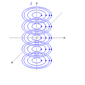
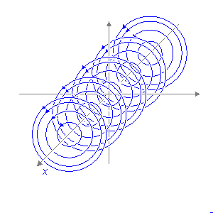
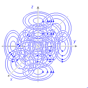
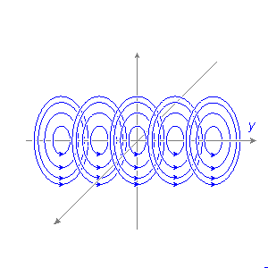
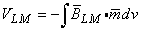
Fig. 12.5. The three components of the lead field
LM of an ideal lead system detecting the magnetic dipole moment of a volume source.Physiological Meaning of Magnetic Dipole
The sensitivity distribution (i.e., the lead field), illustrated in Figure 12.5, is the physiological meaning of the measurement of the (equivalent) magnetic dipole of a volume source.
Similarly as in the detection of the electric dipole moment of a volume source, the concept of "physiological meaning" can be explained in the detection of the magnetic dipole moment of a volume source as follows: When considering the forward problem, the lead field illustrates what is the contribution (effect) of each active cell to the signals of the lead system. When one is considering the inverse problem, the lead field illustrates similarly the most probable distribution and orientation of active cells when a signal is detected in a lead.
12.6 SYNTHESIZATION OF THE IDEAL LEAD FIELD FOR THE DETECTION OF THE MAGNETIC DIPOLE MOMENT OF A VOLUME SOURCE
PRECONDITIONS:
SOURCE: Volume source (at the origin)
CONDUCTOR: Finite, homogeneous with spherical symmetry
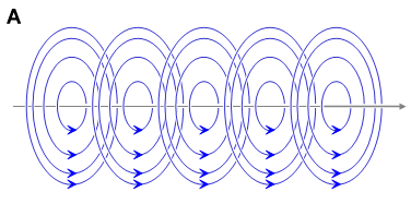
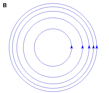
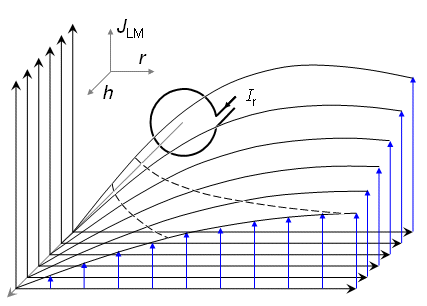
If the dimensions of the volume source are small in relation to the distance to the point of observation, we can consider the magnetic dipole moment to be a contribution from a point source. Thus we consider the magnetic dipole moment to be a discrete vector. The evaluation of such a magnetic dipole is possible to accomplish through unipolar measurements on each coordinate axis as illustrated on the left hand side of Figure 12.6A. If the dimensions of the volume source are large, the quality of the aforementioned lead system is not high. Because the reciprocal magnetic field decreases as a function of distance, the sensitivity of a single magnetometer is higher for source elements locating closer to it than for source elements locating far from it. This is illustrated on the right hand side of Figure 12.6A. In Figure 12.6 the dashed lines represent the reciprocal magnetic field flux tubes. The thin solid circular lines represent the lead field flow lines. The behavior of the reciprocal magnetic field of a single magnetometer coil is illustrated more accurately in Figures 20.14, 20.15, and 22.3.
The result is very much improved if we use symmetric pairs of magnetometers forming bipolar leads, as in Figure 12.6B. This arrangement will produce a reciprocal magnetic field that is more uniform over the source region than is attained with the single coils of the unipolar lead system. (Malmivuo, 1976).
Just as with the electric case, the quality of the bipolar magnetic lead fields in measuring volume sources with large dimensions is further improved by using large coils, whose dimensions are comparable to the source dimensions. This is illustrated in Figure 12.6C..
MAGNETOMETER CONFIGURATION LEAD FIELD OF ONE COMPONENT A UNIPOLAR LEADS, SMALL COILS 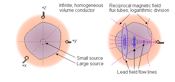
B BIPOLAR LEADS, SMALL COILS 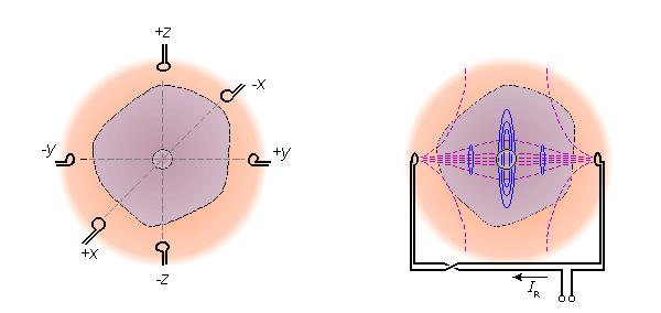
C BIPOLAR LEADS, LARGE COILS 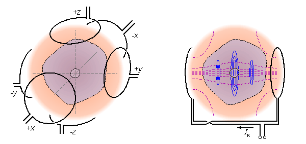
Fig. 12.6. Properties of unipolar and bipolar leads in detecting the equivalent magnetic dipole moment of a volume source. The dashed lines illustrate the isosensitivity lines. The thin solid circular lines represent the lead field flow lines.
(A) If the dimensions of the volume source are small compared to the measurement distance the most simple method is to make the measurement with unipolar leads on the coordinate axes.
(B) For volume sources with large dimensions the quality of the lead field is considerably improved by using symmetric pairs of magnetometers forming bipolar leads.
(C) Increasing the size of the magnetometers further improves the quality of the leads.To describe the behavior of the reciprocal magnetic field and the sensitivity distribution of a bipolar lead as a function of coil separation we illustrate in Figure 12.7 these for two coil pairs with different separation. (Please note, that the isosensitivity lines are not the same as the reciprocal magnetic field lines.) Figure 12.7A illustrates the reciprocal magnetic field as rotational flux tubes for the Helmholtz coils which are a coaxial pair of identical circular coils separated by the coil radius. With this coil separation the radial component of the compound magnetic field at the center plane is at its minimum and the magnetic field is very homogeneous. Helmholtz coils cannot easily be used in detecting biomagnetic fields, but they can be used in magnetization or in impedance measurement. They are used very much in balancing the gradiometers and for compensating the Earth's static magnetic field in the measurement environment. Figure 12.7B illustrates the reciprocal magnetic field flux tubes for a coil pair with a separation of 5r. Figures 12.7C and 12.7D illustrate the isosensitivity lines for the same coils.
Later in Chapter 20, Figure 20.16 illustrates the isosensitivity lines for a coil pair with a separation of 32r. Comparing these two bipolar leads to the Helmholtz coils one may note that in them the region of homogeneous sensitivity is much smaller than in the Helmholtz coils. Due to symmetry, the homogeneity of bipolar leads is, however, much better than that of corresponding unipolar leads.
The arrangement of bipolar lead must not be confused with the differential magnetometer or gradiometer system, which consists of two coaxial coils on the same side of the source wound in opposite directions. The purpose of such an arrangement is to null out the background noise, not to improve the quality of the lead field. The realization of the bipolar lead system with gradiometers is illustrated in Figure 12.8. Later Figure 12.20 illustrates the effect of the second coil on the gradiometer sensitivity distribution for several baselines..

 (A) the Helmholtz coils having a coil separation of r
(B) bipolar lead with a coil separation of 5r.
The isosensitivity lines for
(C) the Helmholtz coils having a coil separation of r
(D) bipolar lead with a coil separation of 5r.
(Note, that the isosensitivity lines are not the same as the flux tubes of the reciprocal magnetic field.).
(A) the Helmholtz coils having a coil separation of r
(B) bipolar lead with a coil separation of 5r.
The isosensitivity lines for
(C) the Helmholtz coils having a coil separation of r
(D) bipolar lead with a coil separation of 5r.
(Note, that the isosensitivity lines are not the same as the flux tubes of the reciprocal magnetic field.).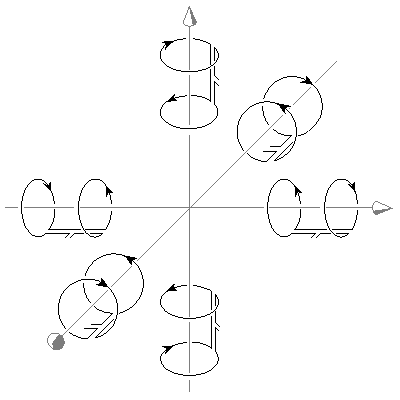
Fig. 12.8. Bipolar lead system for detecting the magnetic dipole moment of a volume source realized with gradiometers.
12.7 COMPARISON OF THE LEAD FIELDS OF IDEAL BIPOLAR LEADS FOR DETECTING THE ELECTRIC AND THE MAGNETIC DIPOLE MOMENTS OF A VOLUME SOURCE
PRECONDITIONS:
SOURCE: Electric and magnetic dipole moments of a volume source
CONDUCTOR: Infinite, homogeneous
12.7.1 The Bipolar Lead System for Detecting the Electric Dipole Moment
LE. (Note the similarity of Figure 11.25, illustrating the reciprocal electric field LE of an electric lead, and Figure 12.7, illustrating the reciprocal magnetic field LM of a magnetic lead.)
12.7.2 The Bipolar Lead System for Detecting the Magnetic Dipole Moment
LM, as described in Figure 12.5.
12.8 THE RADIAL AND TANGENTIAL SENSITIVITIES OF THE LEAD SYSTEMS DETECTING THE ELECTRIC AND MAGNETIC DIPOLE MOMENTS OF A VOLUME SOURCE
PRECONDITIONS:
SOURCE: Electric and magnetic dipole moments of a volume source
CONDUCTOR: Infinite, homogeneous
12.8.1 Sensitivity of the Electric Lead
The radial and tangential sensitivities of the lead system detecting the electric dipole moment of a volume source may be easily estimated for the case where an ideal lead field has been established.
Figure 12.9 describes the cross section of a spherical volume source in an infinite homogeneous volume conductor and two components of the lead field for detecting the electric dipole moment. Let f denote the angle between the horizontal electric lead field flow line and a radius vector from the center of the spherical source to the point at which the radial and tangential source elements ir and it , respectively, lie. According to Equation 11.30, the lead voltage VLE is proportional to the projection of the impressed current density i on the lead field flow line. The sensitivity of the total electric lead is the sum of the sensitivities of the two component leads; hence for the radial component J ir we obtain:
(12.26)
(12.27) We note from Equations 12.26 and 12.27 that the total sensitivity of these two components of the electric lead to radial and tangential current source elements i is equal and independent of their location. The same conclusion also holds in all three dimensions..

Fig. 12.9. Relative sensitivity of the electric lead system to radial and tangential current dipoles
ir and it.12.8.2 Sensitivity of the Magnetic Lead
From Equation 12.13 and from the definition of the magnetic dipole moment of a volume source (see Equation 12.22), it may be seen that the magnetic lead system and its components are sensitive only to tangential source-elements. The magnitude of the sensitivity is, as noted before, proportional to the distance from the symmetry axis.
12.9 SPECIAL PROPERTIES OF THE MAGNETIC LEAD FIELDS
PRECONDITIONS:
SOURCE: Volume source
CONDUCTOR: Finite, inhomogeneous, cylindrically symmetric
Bipolar electric lead Bipolar magnetic lead Bipolar electric and magnetic leads
12.10 THE INDEPENDENCE OF BIOELECTRIC AND BIOMAGNETIC FIELDS AND MEASUREMENTS
12.10.1 Independence of Flow and Vortex Sources
Helmholtz's theorem (Morse and Feshbach, 1953; Plonsey and Collin, 1961) states:
"A general vector field, that vanishes at infinity, can be completely represented as the sum of two independent vector fields; one that is irrotational (zero curl) and another that is solenoidal (zero divergence)."
The impressed current density i is a vector field that vanishes at infinity and, according to the theorem, may be expressed as the sum of two components:

(12.28) iF = 0 and iV = 0.
We first examine the independence of the electric and magnetic signals in the infinite homogeneous case, when the second term on the right-hand side of Equations 7.10 and 12.6, caused by inhomogeneities, is zero. These equations may be rewritten for the electric potential:
(12.29)
(12.30) Substituting Equation 12.28 into Equations 12.29 and 12.30 shows that under homogeneous and unbounded conditions, the bioelectric field arises from iF , which is the flow source (Equation 7.5), and the biomagnetic field arises from iV , which is the vortex source (Equation 12.17). Since the detection of the first biomagnetic field, the magnetocardiogram, by Baule and McFee in 1963 (Baule and McFee, 1963), the demonstration discussed above raised a lot of optimism among scientists. If this independence were confirmed, the magnetic detection of bioelectric activity could bring much new information not available by electric measurement.
Rush was the first to claim that the independence of the electric and magnetic signals is only a mathematical possibility and that physical constraints operate which require the flow and vortex sources, and consequently the electric and magnetic fields, to be fundamentally interdependent in homogeneous volume conductors (Rush, 1975). This may be easily illustrated with an example by noting that, for instance, when the atria of the heart contract, their bioelectric activity produces an electric field recorded as the P-wave in the ECG. At the same time their electric activity produces a magnetic field detected as the P-wave of the MCG. Similarly the electric and magnetic QRS-complexes and T-waves are interrelated, respectively. Thus, full independence between the ECG and the MCG is impossible.
In a more recent communication, Plonsey (1982) showed that the primary cellular source may be small compared to the secondary cellular source and that the latter may be characterized as a double layer source for both the electric scalar and magnetic vector potentials.
12.10.2 Lead Field Theoretic Explanation of the Independence of Bioelectric and Biomagnetic Fields and Measurements
The question of the independence of the electric and magnetic fields of a volume source and the interpretation of Helmholtz's theorem can be better explained using the lead field theory. We discuss this question in connection with the equivalent electric and magnetic dipoles of a volume source. The discussion can, of course, be easily extended to more complex source models as well.
As explained in Section 11.6.6 the electric lead field is given by Equation 11.54. As discussed in Section 11.6.7, the lead system detecting the electric dipole moment of a volume source includes three orthogonal, linear, and homogeneous reciprocal electric fields LE which raise three orthogonal, linear, and homogeneous electric lead fields LE. These three leads are mutually independent and they detect the three orthogonal components of the flow source.
As discussed in Section 12.3 the magnetic lead field is given by Equation 12.11. It was shown in Section 12.5 that the lead system detecting the magnetic dipole moment of a volume source includes three orthogonal, linear, and homogeneous reciprocal magnetic fields LM which raise three orthogonal circular magnetic lead fields LM. These three leads are mutually independent and they detect the three orthogonal components of the vortex source.
In the aforementioned example, due to Helmholtz's theorem, the three independent electric leads are independent of the three independent magnetic leads. In other words, no one of these six leads is a linear combination of the other five. However, in the case of a physiological volume source, the electric and magnetic fields and their three plus three orthogonal components which these six leads detect are not fully independent, because when the source is active, it generates all the three plus three components of the electric and magnetic fields in a way that links them together. Consequently, while all these six leads of a vector-electromagnetic lead system have the capability to sense independent aspects of a source, that capability is not necessarily realized.
It will be shown in Chapter 20 within the discussion of magnetocardiography that when measuring the electric and magnetic dipole moments of a volume source, both methods include three independent leads and include about the same amount of information from the source. The information of these methods is, however, different and therefore the patient groups which are diagnosed correctly with either method are not identical. If in the diagnosis the electric and magnetic signals are used simultaneously, the correctly diagnosed patient groups may be combined and the overall diagnostic performance increases. This may also be explained by noting that in the combined method we have altogether 3 + 3 = 6 independent leads. This increases the total amount of information obtained from the source.
12.11 SENSITIVITY DISTRIBUTION OF BASIC MAGNETIC LEADS
PRECONDITIONS:
SOURCE: Volume source
CONDUCTOR: Finite, inhomogeneous, cylindrically symmetric
12.11.1 The Equations for Calculating the Sensitivity Distribution of Basic Magnetic Leads
Because in an infinite homogeneous volume conductor the magnetic lead field flow lines encircle the symmetry axis, it is easy to calculate the sensitivity distribution of a magnetic lead in a cylindrically symmetric volume conductor, whose symmetry axis coincides with the magnetometer axis. Then the results may be displayed as a function of the distance from the symmetry axis with the distance from the detector as a parameter (Malmivuo, 1976).
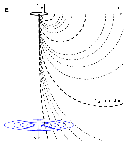
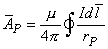
Figure 12.14 illustrates the magnetometer coil L1 and one coaxially situated lead field current flow line L2. The magnetic flux F21 that links the loop L2 due to the reciprocally energizing current Ir in the magnetometer coil is most readily calculated using the magnetic vector potential at the loop L2 (Smythe, 1968, p. 290).
Faraday's law states that a time-varying magnetic field induces electromotive forces whose line integral around a closed loop equals the rate of change of the enclosed flux

(12.31)  da is the magnetic flux evaluated by the integral of the normal component of the magnetic induction across the surface of the loop. For a circular loop the integral on the left-hand side of Equation 12.31 equals 2prE, where r is the radius of the loop, and we obtain for the current density
(12.32) 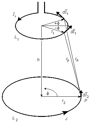
(12.33)
where m = magnetic permeability of the medium rp = distance from the conductor element to the point P is independent of angle f. Therefore, for simplicity, we choose the point P so that f = 0. We notice that when equidistant elements of length d 1 at +f and -f are paired, the resultant is normal to hr. Thus has only the single component Af. If we let dlf be the component of d1 in this direction, then Equation 12.33 may be rewritten as
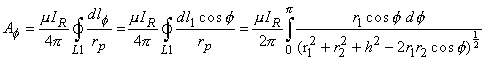
(12.34)
(12.35) With the substitution f = p - 2a , this becomes
(12.36)
(12.37)
(12.38a)
(12.38b)
(12.39a)
(12.39b) Substituting Equation 12.36 into Equation 12.32 gives the lead field current density JLM as a function of the rate of change of the coil current in the reciprocally energized magnetometer:

(12.40) Because we are interested in the spatial sensitivity distribution and not in the absolute sensitivity with certain frequency or conductivity values, the result of Equation 12.40 can be normalized by defining (similarly as was done in Section 12.3.1 in deriving the equation for magnetic lead field)

(12.41)
(12.42) If the distance h is large compared to the coil radius r1 and the lead field current flow line radius r2, the magnetic induction inside the flow line may be considered constant, and Equation 12.42 is greatly simplified. The value of the magnetic flux becomes pr2. Substituting it into Equation 12.32, we obtain
(12.43) 12.11.2 Lead Field Current Density of a Unipolar Lead of a Single-Coil Magnetometer
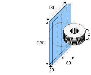
Owing to symmetry, the lead field current density is independent of the angle f in Figure 12.14. Therefore, the lead field current density may be plotted as a function of the radial distance r from the symmetry axis with the distance h from the magnetometer as a parameter. Figure 12.15 shows the lead field current density distribution of a unipolar lead created by a single-coil magnetometer with a 10-mm coil radius in a cylindrically symmetric volume conductor calculated from Equation 12.42. The lead field current density is directed in the tangential direction. (With proper scaling, the figure may be used for studying different measurement distances.)
Figure 12.15 shows that in a unipolar lead the lead field current density is strongly dependent on the magnetometer coil distance. It also shows the small size of the region where the lead field current density increases approximately linearly as a function of the radial distance from the symmetry axis, especially in the vicinity of the coil.
The dashed lines in Figure 12.15 are the isosensitivity lines; these join the points where the lead field current density is 100, 200, 300, 400, and 500 pA/m2, respectively, as indicated by the numbers in italics..
 The effect of the coil radius in a unipolar lead on the lead field current density is shown in Figure 12.17. In this figure, the lead field current density is illustrated for coils with 1 mm, 10 mm, 50 mm, and 100 mm radii. The energizing current in the coils is normalized in relation to the coil area to obtain a constant dipole moment. The 10 mm radius coil is energized with a current of dI/dt = 1 [A/s].
12.11.3 The Effect of the Distal Coil to the Lead Field of a Unipolar Lead
Because of the small signal-to-noise ratio of the biomagnetic signals, measurements are usually made with a first- or second- order gradiometer. The first-order gradiometer is a magnetometer including two coaxial coils separated by a certain distance, called baseline. The coils are wound in opposite directions. Because the magnetic fields of distant (noise) sources are equal in both coils, they are canceled. The magnetic field of a source close to one of the coils produces a stronger signal in the proximal coil (i.e., the coil closer to the source) than in the distal coil (farther from the source), and the difference of these fields is detected. The magnetometer sensitivity to the source is diminished by the distal coil by an amount that is greater the shorter the baseline. The distal coil also increases the proximity effect - that is, the sensitivity of the differential magnetometer as a function of the distance to the source decreases faster than that of a single-coil magnetometer.
Figure 12.18 illustrates the lead field current density for unipolar leads realized with differential magnetometers (i.e., gradiometers). Lead field current density J is illustrated with various baselines as a function of radial distance r from the symmetry axis with the magnetometer distance h as a parameter. The differential magnetometers have a 10 mm coil radius and a 300 mm, 150 mm, 100 mm, and 50 mm baseline..
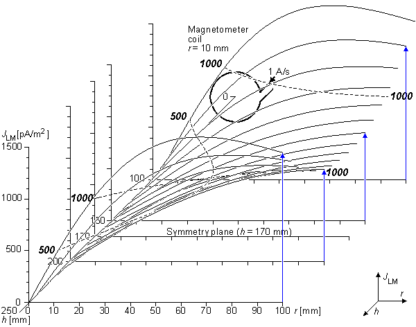
12.11.4 Lead Field Current Density of a Bipolar Lead
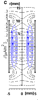
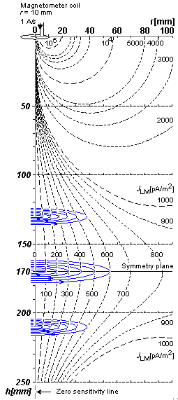
As discussed in Section 12.7 and illustrated in Figure 12.5, when detecting the dipole moment of a volume source with dimensions which are large compared to the measurement distance, the lead field within the source area is much more ideal if a bipolar lead instead of a unipolar one is used. Figure 12.19 shows the lead field current density distribution of a bipolar lead in a cylindrically symmetric volume conductor realized with two coaxial single-coil magnetometers with 10 mm coil radius. The distance between the coils is 340 mm. Note, that in the bipolar lead arrangement the coils are wound in the same direction and the source is located between the coils. The lead field current density as the function of radial distance is lowest on the symmetry plane, i.e. on the plane located in the middle of the two coils. Because the two coils compensate each other's proximity effect, the lead field current density does not change very much as a function of distance from the coils in the vicinity of the symmetry plane. This is illustrated with the isosensitivity line of 500 pA/m2. Therefore the bipolar lead forms a very ideal lead field for detecting the dipole moment of a volume source.
Figure 12.20 illustrates the lead field current density for the bipolar lead of Figure 12.19 with isosensitivity lines. This figure shows still more clearly than the previous one the compensating effect of the two coils in the vicinity of the symmetry plane, especially with short radial distances. The lead field current flows tangentially around the symmetry axis. The flow lines are represented in the figure with thin solid lines..
REFERENCES