4.1 INTRODUCTION
When a stimulus current pulse is arranged to depolarize the resting membrane of a cell to or beyond the threshold voltage, then the membrane will respond with an action impulse. An example of this is seen in Figure 2.8 in the action potential responses 3b and 4 to the transthreshold stimuli 3 and 4, respectively. The response is characterized by an initially rapidly rising transmembrane potential, which reaches a positive peak and then more slowly recovers to the resting voltage. This phasic behavior typifies what is meant by an action impulse.
 A quantitative analysis of the action impulse was successfully undertaken by Alan L. Hodgkin and Andrew F. Huxley and colleagues in Cambridge (Hodgkin and Huxley, 1952abcd). Their work was made possible because of two important factors. The first was the selection of the giant axon of the squid, a nerve fiber whose diameter is around 0.5 mm, and consequently large enough to permit the insertion of the necessary two electrodes into the intracellular space. (Credit for discovering the applicability of the squid axon to electrophysiological studies is given to by J. Z. Young (1936).) The second was the development of a feedback control device called the voltage clamp, capable of holding the transmembrane voltage at any prescribed value.
 This chapter describes the voltage clamp device, the experiments of Hodgkin and Huxley, the mathematical model into which their data were fitted, and the resulting simulation of a wide variety of recognized electrophysiological phenomena (activation, propagation, etc.). The voltage clamp procedure was developed in 1949 separately by K. S. Cole (1949) and G. Marmont (1949). Because of its importance, we first discuss the principle of the voltage clamp method in detail. The Hodgkin and Huxley work is important not only for its ability to describe quantitatively both the active and the passive membrane, but for its contribution to a deeper understanding of the membrane mechanisms that underlie its electrophysiological behavior.
 A remarkable improvement in the research of membrane electrophysiology was made by Erwin Neher and Bert Sakmann, who in 1976 published a method for the measurement of ionic currents in a single ionic channel (Neher and Sakmann, 1976). This method, called patch clamp, is a further development of the voltage clamp technique. The patch clamp technique allows the researcher to investigate the operation of single ion channels and receptors and has a wide application, for instance, in the pharmaceutical research. By measuring the capacitance of the plasma membrane with the patch clamp technique, the researcher may also investigate the regulation of exocytosis of the cell.
 The electric behavior of the axon membrane is, of course, described by the net ion flow through a great number of ion channels. The ion channels seem to behave "digitally" (as seen in the measurement result of the patch clamp experiment); however, because of the large number of ion channels, the electric currents of a large area of the axon membrane exhibit "analog" behavior, as seen in the measurement result obtained in a voltage clamp experiment.
 Logically, discussion of the electric behavior of the membrane should begin by examining the behavior of single ion channels and then proceed to by explain the electric behavior of the membrane as the summation of the behavior of a large number of its constituent ionic channels. For historical reasons, however, membrane behavior and the voltage clamp method are discussed here first, before ionic channel behavior and the patch clamp method are explored.
4.2 VOLTAGE CLAMP METHOD
4.2.1 Goal of the voltage clamp measurement
In order to describe the activation mechanism quantitatively, one must be able to measure selectively the flow of each constituent ion of the total membrane current. In this section, we describe how this is accomplished by the voltage clamp measurement procedure.
 The following current components arise when the axon is stimulated at one end and the membrane voltage as well as current of a propagating nerve impulse are measured distally:
Note that Io = -Ii.
 Our particular goal is to measure selectively each individual ionic current, especially the sodium and potassium currents. Note that because we examine the ionic currents during the propagating nerve impulse, the membrane resistance (rm) is not constant; hence it is represented by a symbol indicating a variable resistance. Any measurement of membrane current with a propagating nerve impulse, however, will yield the sum of these currents.
 The total membrane current (as illustrated in Figure 4.1) satisfies Equation 3.48, which can be rewritten in the form:
  | (4.1) |
| where | im | = total transmembrane current per unit length [µA/cm axon length] |
| imI | = ionic component of the transmembrane current per unit length [µA/cm axon length] | |
| cm | = membrane capacitance per unit length [µF/cm axon length] | |
| Vm | = membrane voltage [mV] | |
| t | = time [ms] | |
| ri | = intracellular axial resistance per unit length of axon [k /cm axon length] | |
| ro | = interstitial resistance per unit length [k /cm axon length] | |
| x | = distance [cm] |
 By measuring Vm(t) and the propagation velocity Q, we could obtain Vm(t - x/Q) and hence im from Equation 4.1. Although the determination of im is straightforward, the accuracy depends on the uniformity of the preparation as well as knowledge of the parameters ri, ro, and Q. A more satisfactory procedure is based on the elimination of the axial currents.
 By convention Vm, the transmembrane voltage, is taken as the intracellular potential, Fi, relative to the extracellular potential, Fo. That is, Vm = Fi - Fo. Further, the positive direction of transmembrane current is chosen as outward (from the intracellular to the extracellular space). These conventions were adopted in the mid-1950s so that in reading earlier papers one should be alert to encountering an opposite choice. The aforementioned conventions are reflected in Equation 4.1. Also, to maintain consistency with the tradition of drawing electronic circuits, in the equivalent circuits of the cell membrane, the reference terminal, that is the outside of the cell, is selected to be at the bottom and the terminal representing the measured signal, that is the inside of the cell, is at the top. In those figures, where it is appropriate to illustrate the membrane in the vertical direction, the inside of the membrane is located on the left-hand side and the outside on the right-hand side of the membrane.
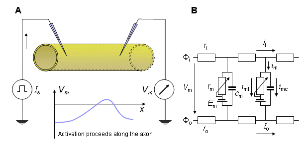
Fig. 4.1. The principle of membrane current measurement with a propagating nerve impulse.
(A) It is assumed that a propagating wave is initiated at the left and has a uniform velocity at the site where the voltage is measured. To obtain the transmembrane current, Equation 4.1 can be used; implementation will require the measurement of the velocity of propagation so that  ²Vm/
²Vm/ x² = (1/Q²)
 ²Vm/
²Vm/ t² can be evaluated.
(B) A portion of the linear core conductor model (assuming the extracellular medium to be bounded) which reflects the physical model above. (Note that because we examine the ionic currents during the propagating nerve impulse, the membrane resistance rm is not constant; hence it is represented by a symbol indicating a variable resistance. To the extent that the ion concentrations may change with time then Em can also be time-varying.) The symbols are explained in the text.
4.2.2 Space clamp
With appropriate instrumentation, it is possible to stimulate the axon simultaneously throughout the entire length of the preparation. Then the membrane voltage at each instant of time is identical over the entire length of the axon. This situation can be brought about by inserting a thin stimulation electrode along the axis of the entire length of the dissected axon, whereas the other electrode, a concentric metal cylinder of the same length, is outside the axon. As a result, there is complete longitudinal uniformity of potential along the axon. This means that the potential can vary only with respect to the radius from the axis, and only radial currents can arise. Furthermore, all membrane elements behave synchronously, so the entire axon membrane behaves as whole. (Hodgkin and Huxley further designed a compartment to eliminate any fringing effects at the ends.) Consequently, between the concentric electrodes, a membrane current will be measured that obeys the equation:
  | (4.2) |
| where | im | = the total current per unit length [µA/cm axon length] |
| imI | = the ionic current per unit length [µA/cm axon length] | |
| cm | = the capacitance of the preparation per unit length [µF/cm axon length] |
Because the apparatus ensures axial uniformity, it is described as space clamped. The electric model of the space clamped measurement is illustrated in Figure 4.2.
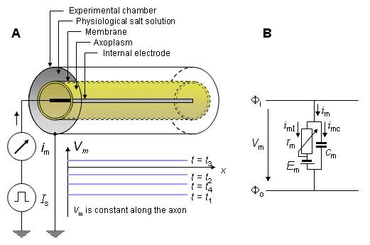
Fig. 4.2. Simplified principle and electric model of the space clamp measurement procedure.
 (A) The physical structure of the device that ensures axial uniformity, hence current flow that is in the radial direction only. The problem is thus reduced to one dimension.
 (B) The total current (im), through the membrane (per unit length), consisting of the components of ionic current imI and capacitive current imC.
4.2.3 Voltage clamp
In the space clamp procedure, the membrane current includes the capacitive component as a confounding source. The capacitive component can be eliminated by keeping the membrane voltage constant during the measurement. Such a procedure is called voltage clamp. Because the capacitive current, the first term on the right side of Equation 4.2, is proportional to the time derivative of the voltage, the capacitive current is zero if the derivative of the voltage is zero. In this case the equation representing the membrane current reduces to:
 im = imI im = imI | (4.3) |
and the membrane current is composed solely of ionic currents. (In the moment following the onset of the voltage step, a very brief current pulse arises owing to the capacitance of the membrane. It disappears quickly and does not affect the measurement of the ensuing activation currents.)
 The voltage clamp procedure is illustrated in the space-clamp device shown in Figure 4.3. A desired voltage step is switched between the inner and outer electrodes, and the current flowing between these electrodes (i.e., the transmembrane current) is measured.
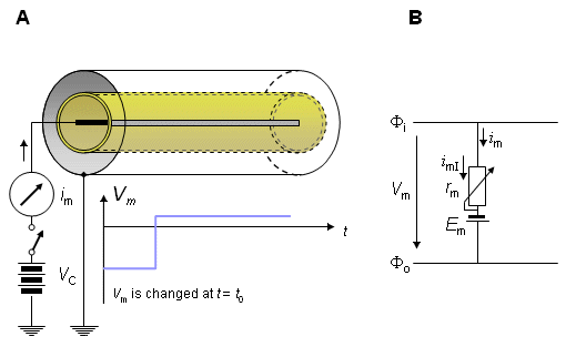
- Fig. 4.3. Voltage clamp experiment.
(A) The simplified principle of the experiment.
(B) Electric model of the axon membrane in voltage clamp experiment.
 The actual voltage clamp measurement circuit is somewhat more complicated than the one described above and is shown in Figure 4.4. Separate electrodes are used for current application (a, e) and voltage sensing (b, c) to avoid voltage errors due to the electrode-electrolyte interface and the resistance of the thin current electrode wires. Figure 4.4 illustrates the principle of the measurement circuit used by Hodgkin, Huxley, and Katz (1952). The circuit includes a unity gain amplifier (having high input impedance), which detects the membrane voltage Vm between a wire inside the axon (b) and outside the axon (c). The output is sent to an adder, where the difference between the clamp voltage (Vc) and the measured membrane voltage (Vm) is detected and amplified. This output, K(Vc - Vm), drives the current generator. The current generator feeds the current to the electrode system (a, e) and hence across the membrane. The current is detected through measurement of the voltage across a calibrated resistance, Rc. The direction of the controlled current is arranged so that Vm is caused to approach Vc, whereupon the feedback signal is reduced toward zero. If K is large, equilibrium will be established with Vm essentially equal to Vc and held at that value. The principle is that of negative feedback and proportional control.
 The measurements were performed with the giant axon of a squid. The thickness of the diameter of this axon - approximately 0.5 mm - makes it possible to insert the two internal electrodes described in Figure 4.4 into the axon. (These were actually fabricated as interleaved helices on an insulating mandrel.).
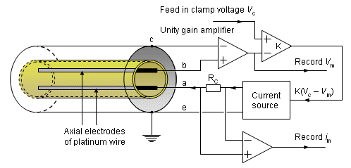
Fig. 4.4. Realistic voltage clamp measurement circuit. Current is applied through electrodes (a) and (e), while the transmembrane voltage, Vm, is measured with electrodes (b) and (c). The current source is controlled to maintain the membrane voltage at some preselected value Vc.
4.3 EXAMPLES OF RESULTS OBTAINED WITH THE VOLTAGE CLAMP METHOD
4.3.1 Voltage clamp to sodium Nernst voltage
Figure 4.5 illustrates a typical transmembrane current obtained with the voltage clamp method. The potential inside the membrane is changed abruptly from the resting potential of -65 mV to +20 mV with an 85 mV step. As a result, an ionic current starts to flow which is inward at first but which, after about 2 ms, turns outward, asymptotically approaching the value 2 mA/cm². Let us examine the membrane current arising with different voltage steps. Figure 4.6 presents the results from experiments comprising five measurements at the voltage steps of 91-143 mV. In the series of curves, it may be noted that the membrane current is again composed of two components - an early and a late behavior as was the case in Figure 4.5.
 The early current is directed inward for the smaller voltage steps. As the voltage step increases, the amplitude of the inward component decreases, and it disappears entirely with the voltage step of 117 mV. With higher voltage steps, the early current is directed outward and increases proportionally to the voltage step. The late component of the membrane current on the other hand is always outward and increases monotonically, approaching an asymptotic limit. This limit grows as a function of the size of the voltage step.
 Assuming a resting membrane voltage of -65 mV, a 117 mV voltage step results in a membrane voltage of +52 mV. Based on the sodium concentration inside and outside the membrane, the Nernst equation evaluates an equilibrium voltage of +50 mV. (Note the example in Section 3.1.3.) Hence one can conclude that the early component of the membrane current is carried by sodium ions since it reduces to zero precisely at the sodium equilibrium voltage and is inward when Vm is less than the sodium Nernst voltage and outward when Vm exceeds the sodium Nernst voltage. The outward (late) component must therefore be due to potassium ion flow. Because chloride tends to be near equilibrium, for the axon at rest while the chloride permeability does not increase during an action potential the chloride current tends to be small relative to that of sodium and potassium and can be ignored..
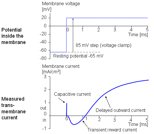
- Fig. 4.5. Voltage step and membrane current in voltage clamp experiment.
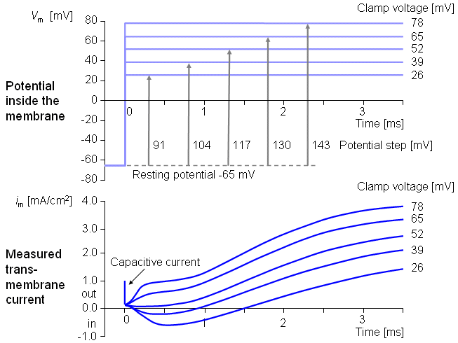
- Fig. 4.6. A series of voltage clamp steps..4.3.2 Altering the ion concentrations
4.3.2 Altering the Ion Concentrations
An approach to the selective measurement of the potassium ion flow alone is available by utilizing a voltage clamp step corresponding to the sodium Nernst potential. This maneuver effectively eliminates sodium flow. By systematically altering the sodium concentration outside the axon, and then choosing the voltage clamp step at the respective sodium Nernst voltage, we can study the behavior of K+ alone. And if we return to the current measurement under normal conditions (with both sodium and potassium), subtracting the potassium current leaves the sodium current alone. This procedure is illustrated in Figure 4.7. This figure shows results from a voltage clamp experiment that was first done in normal seawater with a 56 mV step. Figure 4.7.A illustrates the Nernst potentials for different ions and the clamp voltage. The curve in (B) represents the measured total membrane current consisting of sodium and potassium components. Curve (C) is the membrane current measured after the extracellular sodium ions were reduced so that the 56 mV step reached the (new) sodium Nernst voltage. This curve, consequently, represents only potassium current. By subtracting curve (C) from curve (B), we obtain curve (D), which is the membrane current due to sodium ions in the original (unmodified sodium) situation. Thus curves (C) and (D) are the desired components of (B). Note that Hodgkin and Huxley assumed that the potassium current is unaffected by changes in extracellular sodium so that (C) is the same in both normal and reduced-sodium seawater.
 A very clever technique was also developed by Baker, Hodgkin, and Shaw (1962) which enabled a change to be made in the internal ionic composition as well. Figure 4.8 illustrates how to do the preparation of the axon for the type of experiment conducted by Hodgkin and Huxley. For this experiment, it is first necessary to squeeze out the normal axoplasm; this is accomplished using a roller (A). Then the axon is filled with perfusion fluid (B). The membrane voltage is measured during action impulse before (C) and after (D) the procedures. Measurements following restoration of initial conditions are also performed to ensure that the electric behavior of the axon membrane has not changed..
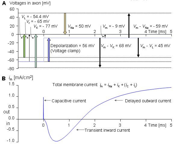
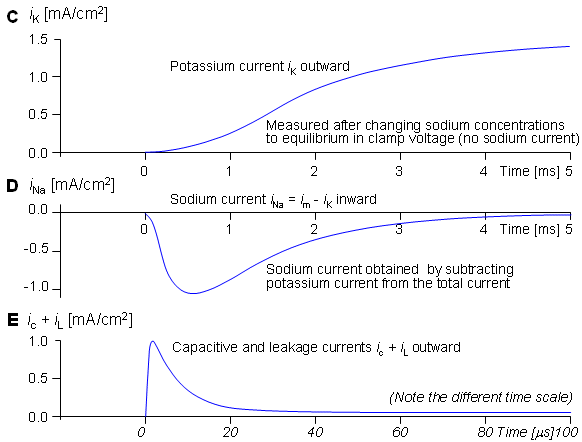
Fig. 4.7. Selective measurement of sodium and potassium current: The extracellular sodium ions are replaced with an inactive cation to reduce the sodium Nernst potential so that it corresponds to the clamp voltage value.
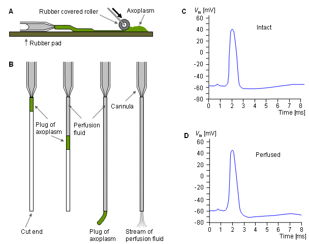
- Fig. 4.8. Preparation of the squid axon for a voltage clamp experiment, where the internal ionic concentrations of the axon are changed.
(A) The axoplasm is first squeezed out with a roller.
(B) The axon is filled with perfusion fluid.
(C) The axon impulse is measured before perfusion.
(D) The axon impulse after perfusion.
4.3.3 Blocking of ionic channels with pharmacological agents
The sodium and potassium currents may also be separated by applying certain pharmacological agents that selectively block the sodium and potassium channels. Narahashi, Moore, and their colleagues showed that tetrodotoxin (TTX) selectively blocks the flow of sodium across the membrane (Narahashi, Moore, and Scott, 1964; Moore et al., 1967). Armstrong and Hille (1972) showed that tetraethylammonium (TEA) blocks the flow of potassium ions. (It may be interesting to know that tetrodotoxin is the poisonous chemical that exists in the viscera of the Japanese fugu fish. The fugu fish is considered as an exotic dish. Before it can be used in a meal, it must be carefully prepared by first removing the poisonous parts.) Figure 4.9 shows a series of voltage clamp experiments, which begin with normal conditions. Then the sodium channels are blocked with tetrodotoxin, and the measurement represents only the potassium current. Thereafter, the tetrodotoxin is flushed away, and a control measurement is made. After this, the potassium channels are blocked with tetraethylammonium which allows selective measurement of the sodium current (Hille, 1970).
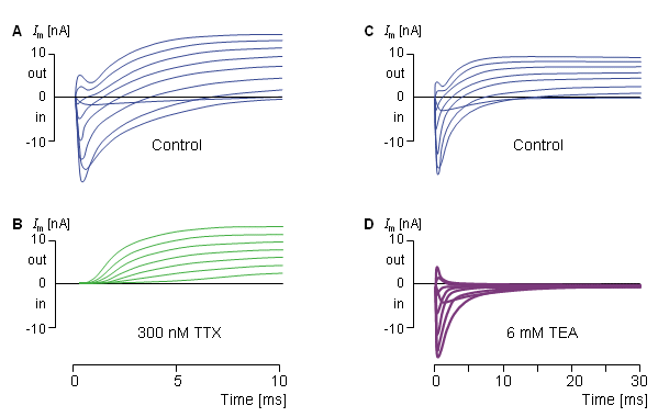
- Fig. 4.9. Selective measurement of sodium and potassium currents by selective blocking of the sodium and potassium channels with pharmacological agents.
(A) Control measurement without pharmacological agents.
(B) Measurement after application of tetrodotoxin (TTX).
(C) Control measurement without pharmacological agents.
(D) Measurement after application of tetraethylammonium (TEA).
4.4 HODGKIN-HUXLEY MEMBRANE MODEL
4.4.1 Introduction
In the following, membrane kinetics is discussed in detail, based on the model by A. L. Hodgkin and A. F. Huxley (1952d). Hodgkin and Huxley's model is based on the results of their voltage clamp experiments on giant axons of the squid. The model is not formulated from fundamental principles but, rather is a combination of theoretical insight and curve fitting. Hodgkin and Huxley described their work by saying:Our object here is to find equations which describe the conductances with reasonable accuracy and are sufficiently simple for theoretical calculation of the action potential and refractory period. For sake of illustration we shall try to provide a physical basis for the equations, but must emphasize that the interpretation given is unlikely to provide a correct picture of the membrane. (Hodgkin and Huxley, 1952d, p. 506)
 In spite of its simple form, the model explains with remarkable accuracy many nerve membrane properties. It was the first model to describe the ionic basis of excitation correctly. For their work, Hodgkin and Huxley received the Nobel Prize in 1963. Although we now know many specific imperfections in the Hodgkin-Huxley model, it is nevertheless essential to discuss it in detail to understand subsequent work on the behavior of voltage-sensitive ionic channels.
 The reader should be aware that the original Hodgkin and Huxley papers were written at a time when the definition of Vm was chosen opposite to the convention adopted in the mid-1950s. In the work described here, we have used the present convention: Vm equals the intracellular minus extracellular potential.
4.4.2 Total membrane current and its components
Hodgkin and Huxley considered the electric current flowing across the cell membrane during activation to be described by what we now call the parallel conductance model (called also the chord conductance model) (Junge, 1992), which for the first time separated several ion-conducting branches. This model is illustrated in Figure 4.10. It consists of four current components:
- Current carried by sodium ions
- Current carried by potassium ions
- Current carried by other ions (designated leakage current, constituting mainly from chloride ions)
- Capacitive (displacement) current
In this model, each of these four current components is assumed to utilize its own (i.e., independent) path or channel. To follow the modern sign notation, the positive direction of membrane current and Nernst voltage is chosen to be from inside to outside.
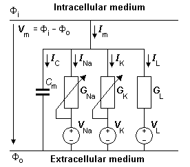
- Fig. 4.10. The equivalent circuit of the Hodgkin-Huxley model. The voltage sources show the polarity of the positive value. The calculated Nernst voltages of sodium, potassium, and chloride designate the value of corresponding voltage sources. With the normal extracellular medium, VNa has a positive value (Equation 4.7) while VK and VL have negative values (Equations 4.8 and 4.9). During an action impulse, GNa and GK vary as a function of transmembrane voltage and time.
 The model is constructed by using the basic electric circuit components of voltage source, resistance, and capacitance as shown in Figure 4.10. The ion permeability of the membrane for sodium, potassium, and other ions (introduced in Equation 3.34) is taken into account through the specification of a sodium, potassium, and leakage conductance per unit area (based on Ohm's law) as follows:
  | (4.4) |
  | (4.5) |
  | (4.6) |
| where | GNa, GK, GL | = membrane conductance per unit area for sodium, potassium, and other ions - referred to as the leakage conductance [S/cm²] |
| INa, IK, IL | = the electric current carried by sodium, potassium and other ions (leakage current) per unit area [mA/cm²] | |
| VNa, VK, VL | = Nernst voltage for sodium, potassium and other ions (leakage voltage) [mV] | |
| Vm | = membrane voltage [mV] |
 The above-mentioned Nernst voltages are defined by the Nernst equation, Equation 3.21, namely:
  | (4.7) |
  | (4.8) |
  | (4.9) |
where the subscripts "i" and "o" denote the ion concentrations inside and outside the cell membrane, respectively. Other symbols are the same as in Equation 3.21 and z = 1 for Na and K but z = -1 for Cl.
 In Figure 4.10 the polarities of the voltage sources are shown as having the same polarity which corresponds to the positive value. We may now insert the Nernst voltages of sodium, potassium, and chloride, calculated from the equations 4.7 ... 4.9 to the corresponding voltage sources so that a calculated positive Nernst voltage is directed in the direction of the voltage source polarity and a calculated negative Nernst voltage is directed in the opposite direction. With the sodium, potassium, and chloride concentration ratios existing in nerve and muscle cells the voltage sources of Figure 4.10 in practice achieve the polarities of those shown in Figure 3.4.
 Because the internal concentration of chloride is very low small movements of chloride ion have a large effect on the chloride concentration ratio. As a result, a small chloride ion flux brings it into equilibrium and chloride does not play an important role in the evaluation of membrane potential (Hodgkin and Horowicz, 1959). Consequently Equation 4.9 was generalized to include not only chloride ion flux but that due to any non-specific ion. The latter flux arises under experimental conditions since in preparing an axon for study small branches are cut leaving small membrane holes through which small amounts of ion diffusion can take place. The conductance GL was assumed constant while VL was chosen so that the sum of all ion currents adds to zero at the resting membrane potential.
 When Vm = VNa, the sodium ion is in equilibrium and there is no sodium current. Consequently, the deviation of Vm from VNa (i.e., Vm - VNa) is a measure of the driving voltage causing sodium current. The coefficient that relates the driving force (Vm - VNa) to the sodium current density INa is the sodium conductance, GNa - that is, INa = GNa(Vm - VNa), consistent with Ohm's law. A rearrangement leads to Equation 4.4. Equations 4.5 and 4.6 can be justified in the same way.
 Now the four currents discussed above can be evaluated for a particular membrane voltage, Vm. The corresponding circuits are formed by:
- Sodium Nernst voltage and the membrane conductance for sodium ions
- Potassium Nernst voltage and the membrane conductance for potassium ions
- Leakage voltage (at which the leakage current due to chloride and other ions is zero) and membrane leakage conductance
- Membrane capacitance
(Regarding these circuit elements Hodgkin and Huxley had experimental justification for assuming linearly ohmic conductances in series with each of the emfs. They observed that the current changed linearly with voltage when a sudden change of membrane voltage was imposed. These conductances are, however, not included in the equivalent circuit in Figure 4.10. (Huxley, 1993))
 On the basis of their voltage clamp studies, Hodgkin and Huxley determined that the membrane conductance for sodium and potassium are functions of transmembrane voltage and time. In contrast, the leakage conductance is constant. Under subthreshold stimulation, the membrane resistance and capacitance may also be considered constant.
 One should recall that when the sodium and potassium conductances are evaluated during a particular voltage clamp, their dependence on voltage is eliminated because the voltage during the measurement is constant. The voltage nevertheless is a parameter, as may be seen when one compares the behavior at different voltages. For a voltage clamp measurement the only variable in the measurement is time. Note also that the capacitive current is zero, because dV/dt = 0.
 For the Hodgkin-Huxley model, the expression for the total transmembrane current density is the sum of the capacitive and ionic components. The latter consist of sodium, potassium, and leakage terms and are given by rearranging Equations 4.4 through 4.6. Thus
  | (4.10) |
| where | Im | = membrane current per unit area [mA/cm²] |
| Cm | = membrane capacitance per unit area [F/cm²] | |
| Vm | = membrane voltage [mV] | |
| VNa, VK, VL | = Nernst voltage for sodium, potassium and leakage ions [mV] | |
| GNa, GK, GL | = sodium, potassium, and leakage conductance per unit area [S/cm²] |
 As noted before, in Figure 4.10 the polarities of the voltage sources are shown in a universal and mathematically correct way to reflect the Hodgkin-Huxley equation (Equation 4.10). With the sodium, potassium, and chloride concentration ratios existing in nerve and muscle cells the voltage sources of Figure 4.10 in practice achieve the polarities of those shown in Figure 3.4.
 Note that in Equation 4.10, the sum of the current components for the space clamp action impulse is necessarily zero, since the axon is stimulated simultaneously along the whole length and since after the stimulus the circuit is open. There can be no axial current since there is no potential gradient in the axial direction at any instant of time. On the other hand, there can be no radial current (i.e., Im = 0) because in this direction there is an open circuit. In the voltage clamp experiment the membrane current in Equation 4.10 is not zero because the voltage clamp circuit permits a current flow (necessary to maintain the clamp voltage).
4.4.3 Potassium conductance
Because the behavior of the potassium conductance during the voltage clamp experiment is simpler than that of the sodium conductance, it will be discussed first. Hodgkin and Huxley speculated on the ion conductance mechanism by saying that
[it] depends on the distribution of charged particles which do not act as carriers in the usual sense, but which allow the ions to pass through the membrane when they occupy particular sites in the membrane. On this view the rate of movement of the activating particles determines the rate at which the sodium and potassium conductances approach their maximum but has little effect on the (maximum) magnitude of the conductance. (Hodgkin and Huxley, 1952d, p. 502)
 Hodgkin and Huxley did not make any assumptions regarding the nature of these particles in chemical or anatomical terms. Because the only role of the particles is to identify the fraction of channels in the open state, this could be accomplished by introducing corresponding abstract random variables that are measures of the probabilities that the configurations are open ones. In this section, however, we describe the Hodgkin-Huxley model and thus follow their original idea of charged particles moving in the membrane and controlling the conductance. (These are summarized later in Figure 4.13.)
 The time course of the potassium conductance (GK) associated with a voltage clamp is described in Figure 4.11 and is seen to be continuous and monotonic. (The curves in Figure 4.11 are actually calculated from the Hodgkin-Huxley equations. For each curve the individual values of the coefficients, listed in Table 1 of Hodgkin and Huxley (1952d), are used; therefore, they follow closely the measured data.) Hodgkin and Huxley noted that this variation could be fitted by a first-order equation toward the end of the record, but required a third- or fourth-order equation in the beginning. This character is, in fact, demonstrated by its sigmoidal shape, which can be achieved by supposing GK to be proportional to the fourth power of a variable, which in turn satisfies a first-order equation. Hodgkin and Huxley gave this mathematical description a physical basis with the following assumptions.
 As is known, the potassium ions cross the membrane only through channels that are specific for potassium. Hodgkin and Huxley supposed that the opening and closing of these channels are controlled by electrically charged particles called n-particles. These may stay in a permissive (i.e., open) position (for instance inside the membrane) or in a nonpermissive (i.e., closed) position (for instance outside the membrane), and they move between these states (or positions) with first-order kinetics. The probability of an n-particle being in the open position is described by the parameter n, and in the closed position by (1 - n), where 0
  n
n  1. Thus, when the membrane potential is changed, the changing distribution of the n-particles is described by the probability of n relaxing exponentially toward a new value.
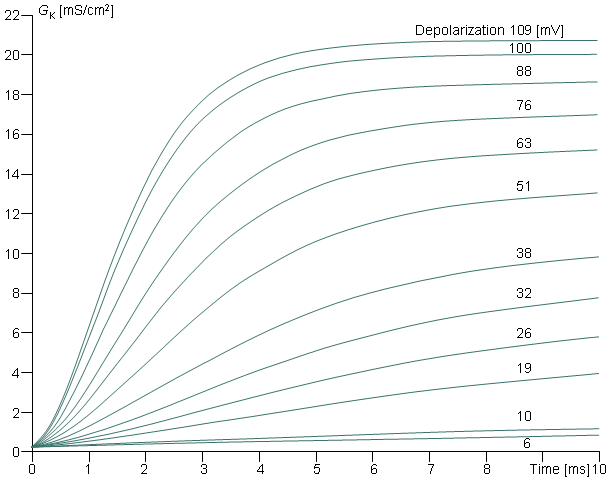
Fig. 4.11. Behavior of potassium conductance as a function of time in a voltage clamp experiment. The displacement of transmembrane voltage from the resting value [in mV] is shown (all are depolarizations). These theoretical curves correspond closely to the measured values.
 In mathematical form, the voltage- and time-dependent transitions of the n-particles between the open and closed positions are described by the changes in the parameter n with the voltage-dependent transfer rate coefficients an and bn. This follows a first-order reaction given by :
  | (4.11) |
| where | an | = the transfer rate coefficient for n-particles from closed to open state [1/s] |
| bn | = the transfer rate coefficient for n-particles from open to closed state [1/s] | |
| n | = the fraction of n-particles in the open state | |
| 1 - n | = the fraction of n-particles in the closed state |
 If the initial value of the probability n is known, subsequent values can be calculated by solving the differential equation
  | (4.12) |
Thus, the rate of increase in the fraction of n-particles in the open state dn/dt depends on their fraction in the closed state (1 - n), and their fraction in the open state n, and on the transfer rate coefficients an and bn. Because the n-particles are electrically charged, the transfer rate coefficients are voltage-dependent (but do not depend on time). Figure 4.12A shows the variations of the transfer rate coefficients with membrane voltage. Expressions for determining their numerical values are given at the end of this section.
 Furthermore Hodgkin and Huxley supposed that the potassium channel will be open only if four n-particles exist in the permissive position (inside the membrane) within a certain region. It is assumed that the probability of any one of the four n-particles being in the permissive position does not depend on the positions of the other three. Then the probability of the channel being open equals the joint probability of these four n-particles being at such a site and, hence, proportional to n4. (These ideas appear to be well supported by studies on the acetylcholine receptor, which consists of five particles surrounding an aqueous channel, and where a small cooperative movement of all particles can literally close or open the channel (Unwin and Zampighi, 1980).)
 The potassium conductance per unit area is then the conductance of a single channel times the number of open channels. Alternatively, if GK max is the conductance per unit area when all channels are open (i.e., its maximum value), then if only the fraction n4 are open, we require that
  | (4.13) |
where GK max = maximum value of potassium conductance [mS/cm²], and n obeys Equation 4.12.
 Equations 4.12 and 4.13 are among the basic expressions in the Hodgkin and Huxley formulation.
Equation for n at voltage clamp
For a voltage step (voltage clamp), the transfer rate coefficients an and bn change immediately to new (but constant) values. Since at a constant voltage, the transfer rate coefficients in Equation 4.12 are constant, the differential equation can be readily solved for n, giving
  | (4.14) |
| where |  | = steady-state value of n |
 | = time constant [s] |
We see that the voltage step initiates an exponential change in n from its initial value of n0 (the value of n at t = 0) toward the steady-state value of n (the value of n at t =
  ). Figure 4.12B shows the variation of n
 and n
and n 4 with membrane voltage.
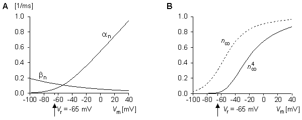
Fig. 4.12. (A) Variation of transfer rate coefficients an and bn as functions of membrane voltage.
(B) Variation of n and n
and n 4 as functions of membrane voltage (GK
  n4 ).
n4 ).
Summary of the Hodgkin-Huxley model for potassium conductance
Figure 4.13 presents an interpretation of the ideas of the Hodgkin-Huxley model for potassium conductance though representing the authors' interpretation. In Figure 4.13A the response of the n-particles to a sudden depolarization is shown before and at two successive instants of time during the depolarization. Initially, the fraction of n-particles in the permissive position (inside the membrane), n, is small since an is small and bn is large. Therefore, the potassium channels (of which two are illustrated) are closed. Depolarization increases an and decreases bn so that n rises exponentially (following first-order kinetics) toward a maximum value of n . When four n-particles occupy the site around the channel inside the membrane, the channel opens; therefore, the potassium conductance GK is proportional to n4, as shown in Equation 4.13. Figure 4.13A illustrates this phenomenon first at one channel and then at two channels. The magnitude of an and bn is shown in Figures 4.13A by the thickness of the arrows and in 4.13B by the curves. In Figure 4.13C, the response of n and n4 to a sudden depolarization and repolarization is shown.
 The reader may verify that the potassium conductance really is proportional to n4, by comparing this curve and the curve in Figure 4.11 representing the potassium conductance at 88 mV depolarization (which is the value closest to 85 mV used in Figure 4.13). These curves are very similar in form.
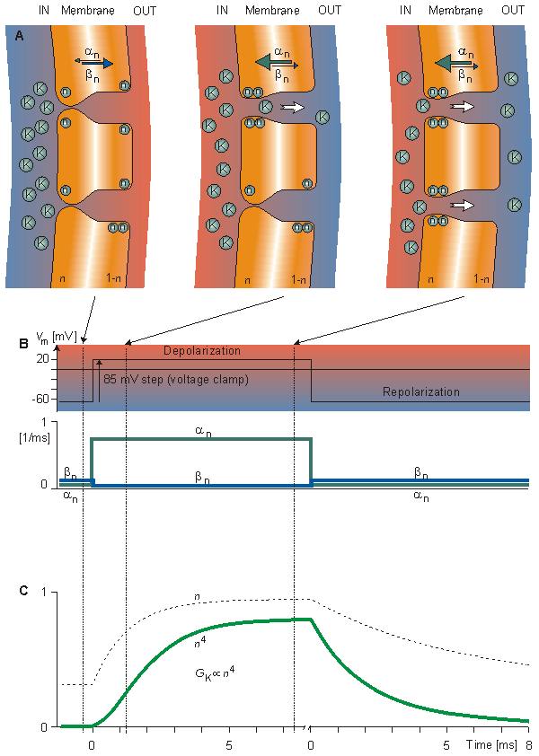
Fig. 4.13. In the Hodgkin-Huxley model, the process determining the variation of potassium conductance with depolarization and repolarization with voltage clamp.
(A) Movement of n-particles as a response to sudden depolarization. Initially, an is small and bn is large, as indicated by the thickness of the arrows. Therefore, the fraction n of n-particles in the permissive state (inside the membrane) is small. Depolarization increases an and decreases bn. Thus n rises exponentially to a larger value. When four n-particles occupy the site around the channel inside the membrane, the channel opens.
(B) The response of the transfer rate coefficients an and bn to sudden depolarization and repolarization.
(C) The response of n and n4 to a sudden depolarization and repolarization (GK  n4 )
n4 )
4.4.4 Sodium conductance
The results that Hodgkin and Huxley obtained for sodium conductance in their voltage clamp experiments are shown in Figure 4.14 (Hodgkin and Huxley, 1952d). The curves in Figure 4.14 are again calculated from the Hodgkin-Huxley equations and fit closely to the measured data. The behavior of sodium conductance is initially similar to that of potassium conductance, except that the speed of the conductance increase during depolarization is about 10 times faster. The rise in sodium conductance occurs well before the rise in potassium conductance becomes appreciable. Hodgkin and Huxley assumed again that at the sodium channels certain electrically charged particles called m-particles exist whose position control the opening of the channel. Thus they have two states, open (permissive) and closed (nonpermissive); the proportion m expresses the fraction of these particles in the open state (for instance inside the membrane) and (1 - m) the fraction in the closed state (for instance outside the membrane), where 0
  m
m  1.
1.
 The mathematical form for the voltage- and time-dependent transitions of the m-particles between the open and closed positions is similar to that for potassium. We identify these with a subscript "m"; thus the voltage-dependent transfer rate coefficients are am and bm. These follow a first-order process given by
  | (4.15) |
| where | am | = the transfer rate coefficient for m-particles from closed to open state [1/s] |
| bm | = the transfer rate coefficient for m-particles from open to closed state [1/s] | |
| m | = the fraction of m-particles in the open state | |
| 1 - m | = the fraction of m-particles in the closed state |
 An equation for the behavior of sodium activation may be written in the same manner as for the potassium, namely that m satisfies a first-order process:
  | (4.16) |
The transfer rate coefficients am and bm are voltage-dependent but do not depend on time..
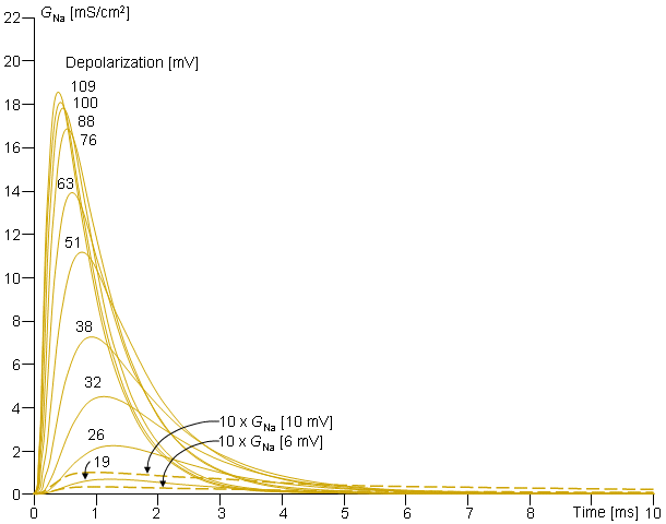
Fig. 4.14. Behavior of sodium conductance in voltage clamp experiments. The clamp voltage is expressed as a change from the resting value (in [mV]). Note that the change in sodium conductance is small for subthreshold depolarizations but increases greatly for transthreshold depolarization (  Vm = 26 mV).
On the basis of the behavior of the early part of the sodium conductance curve, Hodgkin and Huxley supposed that the sodium channel is open only if three m-particles are in the permissive position (inside the membrane). Then the probability of the channel being open equals the joint probability that three m-particles in the permissive position; hence the initial increase of sodium conductance is proportional to m3.
 The main difference between the behavior of sodium and potassium conductance is that the rise in sodium conductance, produced by membrane depolarization, is not maintained. Hodgkin and Huxley described the falling conductance to result from an inactivation process and included it by introducing an inactivating h-particle. The parameter h represents the probability that an h-particle is in the non-inactivating (i.e., open) state - for instance, outside the membrane. Thus (1 - h) represents the number of the h-particles in the inactivating (i.e., closed) state - for instance, inside the membrane. The movement of these particles is also governed by first-order kinetics:
  | (4.17) |
| where | ah | = the transfer rate coefficient for h-particles from inactivating to non-inactivating state [1/s] |
| bh | = the transfer rate coefficient for h-particles from non-inactivating to inactivating state [1/s] | |
| h | = the fraction of h-particles in the non-inactivating state | |
| 1 - h | = the fraction of h-particles in the inactivating state |
and satisfies a similar equation to that obeyed by m and n, namely:
  | (4.18) |
Again, because the h-particles are electrically charged, the transfer rate coefficients ah and bh are voltage-dependent but do not depend on time.
 The sodium conductance is assumed to be proportional to the number of sites inside the membrane that are occupied simultaneously by three activating m-particles and not blocked by an inactivating h-particle. Consequently, the behavior of sodium conductance is proportional to m3h, and
  | (4.19) |
| where | GNa max | = maximum value of sodium conductance [mS/cm²], and |
| m | = obeys Equation (4.16), and | |
| h | = obeys Equation (4.18), and |
 Following a depolarizing voltage step (voltage clamp), m will rise with time (from m0 to m
 ) according to an expression similar to Equation 4.14 (but with m replacing n). The behavior of h is just the opposite since in this case it will be found that h0
  h
h and an exponential decrease results from the depolarization.
Thus the overall response to a depolarizing voltage ste includes an exponential rise in m (and thus a sigmoidal rise in m3 ) and an exponential decay in h so that GNa, as evaluated in Equation 4.19, will first increase and then decrease. This behavior is just exactly that needed to fit the data described in Figure 4.14. In addition, it turns out that the normal resting values of m are close to zero, whereas h is around 0.6. For an initial hyperpolarization, the effect is to decrease m; however, since it is already very small, little additional diminution can occur. As for h, its value can be increased to unity, and the effect on a subsequent depolarization can be quite marked. This effect fits experimental observations closely. The time constant for changes in h is considerably longer than for m and n, a fact that can lead to such phenomena as "anode break," discussed later in this chapter. Figure 4.15A shows variations in the transfer rate coefficients am, bm, ah, and bh with membrane voltage. Figure 4.15B shows the variations in m
 , h
, h , and m
 3 h
3 h with membrane voltage.
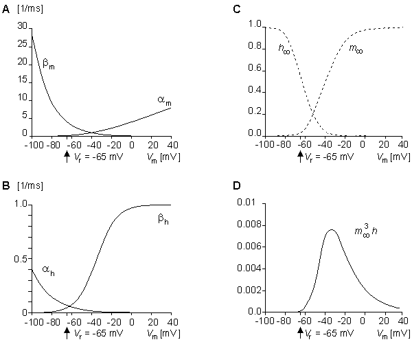
Fig. 4.15. Variation in (A) am and bm, (B) ah and bh, (C) m and h
and h , and (D) m
 3h
3h as a function of membrane voltage. Note that the value of m
 3h
3h is so small that the steady-state sodium conductance is practically zero.
Summary of the Hodgkin-Huxley model for sodium conductance
Similar to Figure 4.13, Figure 4.16 summarizes the voltage clamp behavior of the Hodgkin-Huxley model but for sodium conductance. Figure 4.16A shows the response of the m- and h-particles to a sudden depolarization at rest and at two successive moments during depolarization. (Because the h-particles have inactivating behavior, they are drawn with negative color (i.e., a white letter on a filled circle).) Initially, the fraction of m-particles in the permissive position (inside the membrane), m, is small since am is small and bm is large. Therefore, the sodium channels (of which two are illustrated) are not open. Initially, the fraction of h-particles in the non-inactivating (open-channel) position (outside the membrane), h, is large since is large and h is small. Depolarization increases am and bh, and decreases bm and ah, as shown in Figure 4.16A by the thickness of the arrows and in 4.16B by the curves. Because the time constant tm is much shorter than th, m rises faster toward a maximum value of unity than h decays toward zero. Both parameters behave exponentially (following first-order kinetics) as seen from Figure 4.16C. When three m-particles occupy the site around the channel inside the membrane and one h-particle occupies a site outside the membrane, the channel opens. Therefore, the initial increase of sodium conductance GNa is proportional to m3 (since initially h is large and the non-inactivating h-particles occupy the open-channel site outside the membrane). In figure 4.16A, the short time constant tm is indicated by the almost simultaneous opening of two sodium channels. Later on, because of the longer time constant h, the inactivating h-particles move to the inside of the membrane, blocking the sodium channels. Consequently, as shown in Equation 4.19, the overall behavior of the sodium conductance GNa is proportional to m3h.
 The reader may again verify that the sodium conductance is proportional to m3h by comparing this curve and the curve in Figure 4.14, representing the sodium conductance at 88 mV depolarization (which is the value closest to 85 mV used in Figure 4.16).
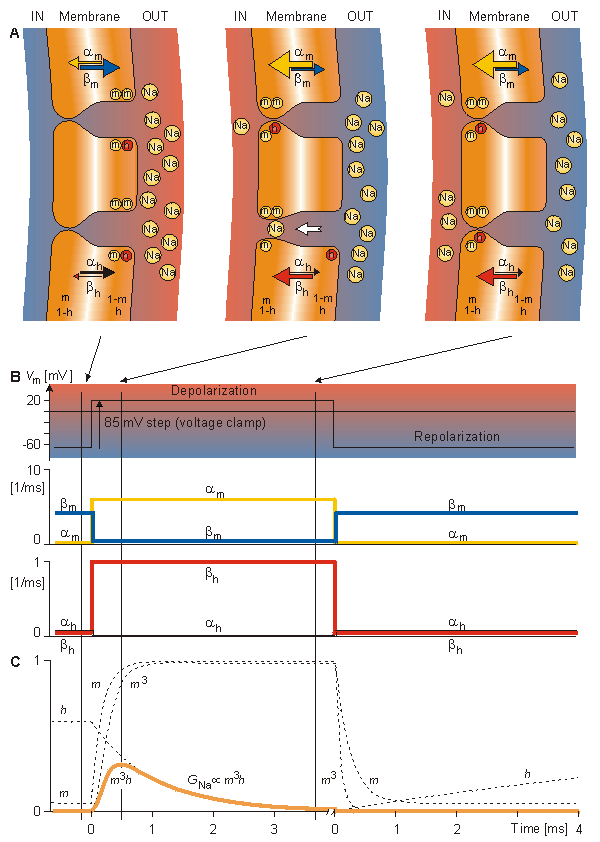
Fig. 4.16. The process, in the Hodgkin-Huxley model, determining the variation of sodium conductance with depolarization and repolarization with voltage clamp.
(A) Movement of m- and h-particles as a response to sudden depolarization. Initially, am is small and bm is large, as indicated by the thickness of the arrows. Therefore, the fraction of particles of type m in the permissive state (inside the membrane) is small. Initially also the value of ah is large and bh is small. Thus the h-particles are in the non-inactivating position, outside the membrane. Depolarization increases am and bh and decreases bm and ah. Thus the number of m-particles inside the membrane, m, rises exponentially toward unity, and the number of h-particles outside the membrane, h, decreases exponentially toward zero.
(B) The response of transfer rate coefficients am, bm, ah, and bh to sudden depolarization and repolarization. (C) The response of m, h, m3, and m3h to a sudden depolarization and repolarization. Note that according to Equation 4.20, GNa is proportional to m3h.
4.4.5 Hodgkin-Huxley equations
Transfer rate coefficients
The transfer rate coefficients a and b of the gating variables n, m, and h are determined from Equations 4.20 through 4.25. These equations were developed by Hodgkin and Huxley and, when substituted into Equations 4.12, 4.14 (and similar ones for m and h), 4.16, and 4.18, lead to the curves plotted in Figures 4.11 and 4.13. This compares well to measurements on the entire range of voltage clamp values. The dimension is [1/ms] for the transfer rate coefficients a and b.
  | (4.20) |
  | (4.21) |
  | (4.22) |
  | (4.23) |
  | (4.24) |
  | (4.25) |
In these equations V' = Vm - Vr, where Vr is the resting voltage. All voltages are given in millivolts. Therefore, V' is the deviation of the membrane voltage from the resting voltage in millivolts, and it is positive if the potential inside the membrane changes in the positive direction (relative to the outside). The equations hold for the giant axon of the squid at a temperature of 6.3 °C.
 Please note again that in the voltage clamp experiment the a and b are constants because the membrane voltage is kept constant during the entire procedure. During an unclamped activation, where the transmembrane voltage is continually changing, the transfer rate coefficients will undergo change according to the above equations.
Constants
In addition to the variables discussed above, the constants of the Hodgkin-Huxley model are given here. The voltages are described in relation to the resting voltage (as shown):
| Cm | = | 1 | µF/cm² |
| Vr - VNa | = | -115 | mV |
| Vr - VK | = | +12 | mV |
| Vr - VL | = | -10.613 | mV |
| GNa max | = | 120 | mS/cm² |
| GK max | = | 36 | mS/cm² |
| GL | = | 0.3 | mS/cm² |
 Note that the value of VL is not measured experimentally, but is calculated so that the current is zero when the membrane voltage is equal to the resting voltage. The voltages in the axon are illustrated in Figure 4.17 in graphical form.
 In Table 4.1 we summarize the entire set of Hodgkin-Huxley equations that describe the Hodgkin-Huxley model..
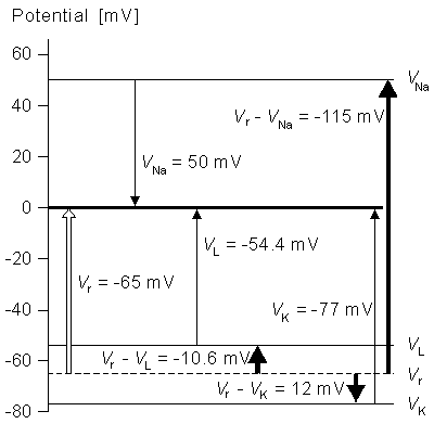
- Fig. 4.17. An illustration of the voltages in the squid axon.
TRANSMEMBRANE CURRENT  IONIC CONDUCTANCES | |
| GNa = GNa max m3h |   |
| GK = GK max n4 GL = constant |  |
| TRANSFER RATE COEFFICIENTS | |
   |    |
| CONSTANTS | |
| Vr - VNa = -115 Vr - VK = +12 Vr - VL = -10.613 mV |
Cm = 1 mF/cm² GNa max = 120 ms/cm² GK max = 36 ms/cm² GL = 0.3 ms/cm² |
4.4.6 Propagating nerve impulse
When analyzing the propagating nerve impulse instead of the nonpropagating activation (i.e., when the membrane voltage is in the space clamp condition), we must consider the axial currents in addition to the transmembrane currents. Let us examine Figure 4.18 (Plonsey, 1969).
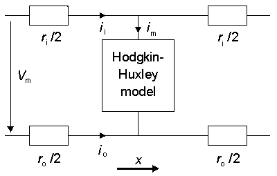
Fig. 4.18. Application of the Hodgkin-Huxley model to a propagating nerve impulse.
 The figure illustrates the model for a unit length of axon. In the model the quantities ri and ro represent the resistances per unit length inside and outside the axon, respectively. Between the inside and outside of the membrane, describing the behavior of the membrane, is a Hodgkin-Huxley model. For the circuit in this figure, Equation 3.42 was derived in the previous chapter for the total membrane current, and it applies here as well:
  | (3.42) |
 In an axon with radius a, the membrane current per unit length is
 im = 2paIm [µA/cm axon length] im = 2paIm [µA/cm axon length] | (4.26) |
where Im = membrane current per unit area [µA/cm²].
 The axoplasm resistance per unit length is:
  | (4.27) |
where ri = axoplasm resistivity [kWcm]
 In practice, when the extracellular space is extensive, the resistance of the external medium per unit length, ro, is so small that it may be omitted and thus from Equations 3.42, 4.26, and 4.27 we obtain:
  | (4.28) |
Equation 4.10 evaluates the transmembrane current density based on the intrinsic properties of the membrane while Equation 4.28 evaluates the same current based on the behavior of the "load". Since these expressions must be equal, the Hodgkin-Huxley equation for the propagating nerve impulse may be written:
  | (4.29) |
 Under steady state conditions the impulse propagates with a constant velocity and it maintains constant form; hence it obeys the wave equation:
  | (4.30) |
where Q = the velocity of conduction [m/s].
 Substituting Equation 4.30 into 4.29 permits the equation for the propagating nerve impulse to be written in the form:
  | (4.31) |
This is an ordinary differential equation which can be solved numerically if the value of Q is guessed correctly. Hodgkin and Huxley obtained numerical solutions that compared favorably with the measured values (18.8 m/s).
 With modern computers it is now feasible to solve a parabolic partial differential equation, Equation 4.29, for Vm as a function of x and t (a more difficult solution than for Equation 4.31). This solution permits an examination of Vm during initiation of propagation and at its termination. One can observe changes in velocity and waveform under these conditions. The velocity in this case does not have to be guessed at initially, but can be deduced from the solution.
 The propagation velocity of the nerve impulse may be written in the form:
  | (4.32) |
| where | Q | = propagation velocity [m/s] |
| K | = constant [1/s] | |
| a | = axon radius [cm] | |
| ri | = axoplasm resistivity [Wcm] |
This can be deduced from Equation 4.31 by noting that the equation is unchanged if the coefficient of the first term is held constant (= 1/K), it being assumed that the ionic conductances remain unaffected (Hodgkin, 1954). Equation 4.32 also shows that the propagation velocity of the nerve impulse is directly proportional to the square root of axon radius a in unmyelinated axons. This is supported by experiment; and, in fact, an empirical relation is:
  | (4.33) |
| where | Q | = propagation velocity [m/s] |
| d | = axon diameter [µm] |
This velocity contrasts with that observed in myelinated axons; there, the value is linearly proportional to the radius, as illustrated earlier in Figure 2.12. A discussion of the factors affecting the propagation velocity is given in Jack, Noble, and Tsien (1975).
Membrane conductance changes during a propagating nerve impulse
K. S. Cole and H. J. Curtis (1939) showed that the impedance of the membrane decreased greatly during activation and that this was due almost entirely to an increase in the membrane conductance. That is, the capacitance does not vary during activation. Figure 4.19 illustrates the components of the membrane conductance, namely GNa and GK, and their sum Gm during a propagating nerve impulse and the corresponding membrane voltage Vm. This is a numerical solution of Equation 4.31 (after Hodgkin and Huxley, 1952d)..
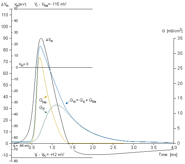
Fig. 4.19. Sodium and potassium conductances (GNa and GK), their sum (Gm), and the membrane voltage (Vm) during a propagating nerve impulse. This is a numerical solution of Equation 4.32 (After Hodgkin and Huxley, 1952d.).
The components of the membrane current during the propagating nerve impulse
Figure 4.20 illustrates the membrane voltage Vm during activation, the sodium and potassium conductances GNa and GK, the transmembrane current Im as well as its capacitive and ionic components ImC and ImI, which are illustrated for a propagating nerve impulse (Noble, 1966). From the figure the following observations can be made:
The potential inside the membrane begins to increase before the sodium conductance starts to rise, owing to the local circuit current originating from the proximal area of activation. In this phase, the membrane current is mainly capacitive, because the sodium and potassium conductances are still low.
The local circuit current depolarizes the membrane to the extent that it reaches threshold and activation begins.
The activation starts with an increasing sodium conductance. As a result, sodium ions flow inward, causing the membrane voltage to become less negative and finally positive.
The potassium conductance begins to increase later on; its time course is much slower than that for the sodium conductance.
When the decrease in the sodium conductance and the increase in the potassium conductance are sufficient, the membrane voltage reaches its maximum and begins to decrease. At this instant (the peak of Vm), the capacitive current is zero (dV/dt = 0) and the membrane current is totally an ionic current.
The terminal phase of activation is governed by the potassium conductance which, through the outflowing potassium current, causes the membrane voltage to become more negative. Because the potassium conductance is elevated above its normal value, there will be a period during which the membrane voltage is more negative than the resting voltage - that is, the membrane is hyperpolarized.
Finally, when the conductances reach their resting value, the membrane voltage reaches its resting voltage..
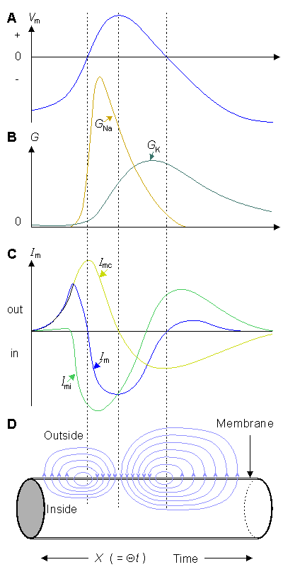
Fig. 4.20. Sodium and potassium conductances GNa and GK, the ionic and capacitive components ImI and ImC of the membrane current Im, and the membrane voltage Vm during a propagating nerve impulse.
4.4.7 Properties of the Hodgkin-Huxley model
The form of a nonpropagating nerve impulse
Figure 4.21 shows both calculated (upper) and measured (lower) membrane voltages at 6 °C temperature for an active membrane during a nonpropagating nerve impulse (space clamp) (Hodgkin and Huxley, 1952d). The calculated curves are numerical solutions of Equation 4.10. The values in the curves indicate the stimulus intensity and are expressed in [nC/cm²]. We note from the figure that the calculated values differ very little from the measured values. There are, however, the following minor differences, namely that the calculated curves have:
- Sharper peaks
- A small downward deflection at the end of the recovery period
Effect of temperature
Figure 4.22 shows both calculated (upper) membrane voltage at 18.5 °C temperature and measured (lower) membrane voltage at 20.5 °C temperature. Both curves have the same voltage axis, but the effect of temperature is corrected on the time axis. In this case, the same errors can be seen in the calculated membrane voltage as in the previous case. However, the correction of the rate constants with the factor 3.48 has maintained the equality of the curves. The effect of the temperature is taken care in the model so that the right-hand sides of the Equations 4.12, 4.16, and 4.18 are multiplied by the factor
 3 (T - 6 . 3)/10 3 (T - 6 . 3)/10 | (4.33) |
where T is the temperature in °C.
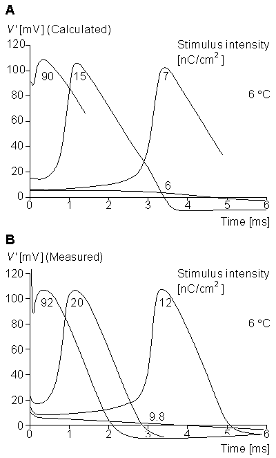
Fig. 4.21. Membrane voltage during a nonpropagating nerve impulse of a squid axon
(A) calculated from Equation 4.10 with Im = 0 and
(B) measured (lower) at 6 °C temperature.
The numbers indicate the stimulus intensity in [nC/cm²]. Note the increasing latency as the stimulus is decreased until, finally, the stimulus falls below threshold.
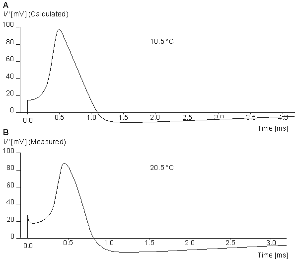
- Fig. 4.22. The membrane voltage
(A) calculated for the initial depolarization of 15 mV at a temperature of 18.5 °C, and
(B) measured at 20.5 °C.
Vertical scales are the same. The horizontal scales differ by a factor appropriate to the temperature difference.
The form of a propagating nerve impulse
The propagating nerve impulse calculated from Equation 4.31 corresponds, accurately, to the measured one. The form of the simulated propagating nerve impulse is illustrated in Figure 4.23A, (Hodgkin and Huxley, 1952d). The corresponding membrane voltage measured at 18.5 °C is given in Figure 4.23B.Refractory period
The Hodgkin-Huxley model also provides an explanation of the refractory period. Figures 4.17 and 4.18 show that the potassium conductance returns to the value corresponding to the resting state only after several milliseconds following initiation of activation. Since activation requires that the (inward) sodium current exceeds the (outward) potassium current, the sodium conductance must reach a relatively higher value during the recovery interval. This requires a stronger stimulus (i.e., the threshold must be elevated). The period being described is known as the relative refractory period. A second factor that explains the refractory behavior is the fact that following depolarization the sodium inactivation parameter, h, diminishes and recovers its resting value slowly. As a result, the likelihood of premature reexcitation of the membrane is further decreased. Figure 4.24 illustrates the calculated and measured response for a stimulus during the refractory period (Hodgkin and Huxley, 1952d). The curves at Figure 4.24A show the response calculated from Equation 4.10 at 6 °C temperature. The axon is first stimulated with a stimulus intensity of 15 nC/cm² which produces an action pulse (curve A in Figure 4.24A). Then after about 5 ms another stimulus pulse with an intensity of 90 nC/cm² is given. Because the axon is after the action pulse in refractory state, it does not produce an action pulse and only the stimulus artifact, curve B in Figure 4.24A is seen. If the 90 nC/cm² stimulus is given about 6 ms after the first 15 nc/cm² stimulus, the axon produces an activation, curve C, though lower with amplitude than the first one. If the second stimulus is given 8 ms after the first one, the response, curve D, is close to the first one. Curve E represents the calculated response to a 90 nC/cm² stimulus when the axon is in the resting state (without the preceding 15 nC/cm² stimulus pulse). (In the curves B-E of Figure 4.24A the values of the response are calculated only for a time of about two milliseconds.) The curves in Figure 4.24B show the corresponding experiments performed with a real axon at 9 C temperature. The time scale is corrected to reflect the temperature difference.
Threshold
Figure 4.25 shows both the calculated and measured threshold at 6 °C for short stimulus pulses. The calculated curves in Figure 4.25A are numerical solutions of Equation 4.10. The values shown indicate the stimulus intensity and are expressed in [nC/cm²]. The figure indicates that the stimulus intensities of 6 nC/cm² or less or a negative value of -10 nC/cm² cannot produce an action pulse while the stimulus intensity of 7 nC/cm² produces it. In the measured data the threshold is 12 nC/cm². The behavior of the model corresponds to a real axon for stimuli both over and under the threshold (Hodgkin and Huxley, 1952d)..
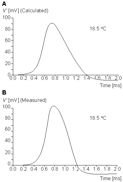
Fig. 4.23. The membrane voltage of a propagating nerve impulse.
(A) Calculated from Equation 4.31. The temperature is 18.5 C and the constant K in Equation 4.32 has the value 10.47 [1/ms].
(B) Measured membrane voltage for an axon at the same temperature as (A).
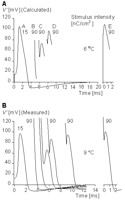
Fig. 4.24. (A) The response during the refractory period calculated from Equation 4.10 at 6 C temperature. The axon is first stimulated with a stimulus intensity of 15 nC/cm², curve A. Curves B, C, and D represent the calculated response to a 90 nC/cm² stimulus at various instants of time after the curve A. Curve E represents the calculated response to a 90 nC/cm² stimulus for an axon in the resting state.
(B) The set of curves shows the corresponding experiments performed with a real axon at 9 C temperature. The time scale is corrected to reflect the temperature difference.
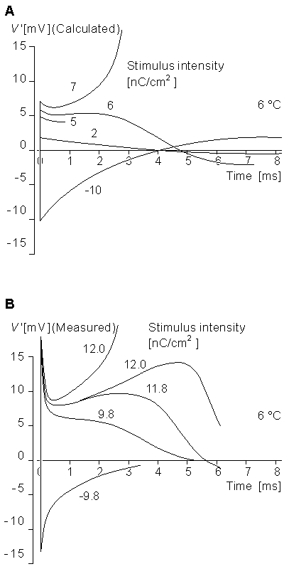
Fig. 4.25. (A) Calculated and (B) measured threshold. The calculated curves are numerical solutions of Equation 4.10. The stimulus intensity is expressed in [nC/cm²].
Anode break
If the membrane voltage is hyperpolarized with a stimulus whose duration exceeds all ionic time constants and then the hyperpolarization is suddenly terminated, the membrane may elicit an action impulse. The Hodgkin-Huxley model illustrates this phenomenon which is called anode break excitation ("anode breakdown" in the original publication). This is described in Figure 4.26. Curve A, the numerical solution of Equation 4.10, illustrates the inside potential of the model when it is made 30 mV more negative than the resting potential at 6 °C. In curve B the resting potential of an actual cell is made 26.5 mV more negative in 18.5 °C (Hodgkin and Huxley, 1952d). In the Hodgkin-Huxley model, the inactivation parameter increases from its normal value of around 0.6 to perhaps 1.0 during the long hyperpolarization. When the voltage is allowed to return to its resting value, its rise causes the sodium activation parameter m to be elevated. But h has a long time constant and tends to remain at its elevated level. The net result is an elevated sodium conductance and elevated sodium current, which can reach the excitatory regenerative behavior even at the normal resting transmembrane voltage. It is also relevant that the potassium conductance (steady-state value of n) is reduced during hyperpolarization, and recovers only with a time course comparable to that of sodium inactivation.
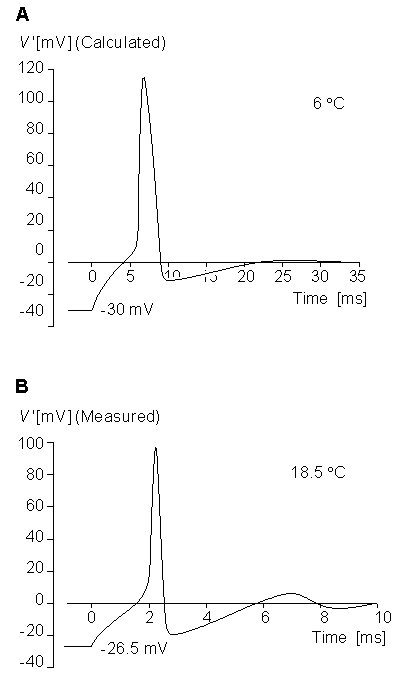
Fig. 4.26. Anode break phenomenon
(A) calculated from Equation 4.10 and
(B) measured from a squid axon at 6 C temperature.
The numbers attached to the curves give the initial depolarization in [mV]. The hyperpolarization is released at t = 0.
4.4.8 The quality of the Hodgkin-Huxley model
A. L. Hodgkin and A. F. Huxley showed that their membrane model describes the following properties of the axon without any additional assumptions (all of these properties were not discussed here):- The form, amplitude, and threshold of the membrane voltage during activation as a function of temperature
- The form, amplitude, and velocity of the propagating nerve impulse
- The change, form, and amplitude of the membrane impedance during activation
- The total sodium inflow (influx) and potassium outflow (efflux) during activation
- Threshold and response during the refractory period
- The amplitude and form of the subthreshold response
- Anode break response
- Adaptation (accommodation)
 On the basis of the facts given in this chapter, the Hodgkin-Huxley model is, without doubt, the most important theoretical model describing the excitable membrane.
4.5 PATCH CLAMP METHOD
4.5.1 Introduction
To elucidate how an ion channel operates, one needs to examine the factors that influence its opening and closing as well as measure the resulting current flow. For quite some time, the challenges involved in isolating a very small membrane area containing just a few (or a single) ion channels, and measuring the extraordinarily small ionic currents proved to be insurmountable. Two cell physiologists, Edwin Neher and Bert Sakmann of the Max Planck Institute (in Göttingen, Germany), succeeded in developing a technique that allowed them to measure the membrane current of a single ion channel. They used a glass microelectrode, called a micropipette, having a diameter of the order of 1 µm. It is said that by accident they placed the electrode very close to the cell membrane so that it came in tight contact with it. The impedance of the measurement circuit then rose to about 50 GW (Neher and Sakmann, 1976). The current changes caused by single ion channels of the cell could then be measured by the voltage clamp method. This device came to be known as a patch clamp since it examined the behavior of a "patch" of membrane; it constitutes an excellent "space clamp" configuration.
 The patch clamp method was further developed to measure the capacitance of the cell membrane (Neher and Marty, 1982). Since the membrane capacitance is proportional to the membrane surface, an examination of minute changes in membrane surface area became possible. This feature has proven useful in studying secretory processes. Nerve cells, as well as hormone-producing cells and cells engaged in the host defense (like mast cells), secrete different agents. They are stored in vesicles enclosed by a membrane. When the cell is stimulated, the vesicles move to the cell surface. The cell and vesicle membranes fuse, and the agent is liberated. The mast cell secretes histamine and other agents that give rise to local inflammatory reactions. The cells of the adrenal medulla liberate the stress hormone adrenaline, and the beta cells in the pancreas liberate insulin. Neher elucidated the secretory processes in these cell types through the development of the new technique which records the fusion of the vesicles with the cell membrane. Neher realized that the electric properties of a cell would change if its surface area increased, making it possible to record the actual secretory process. Through further developments of their sophisticated equipment, its high resolution finally permitted recording of individual vesicles fusing with the cell membrane. Neher and Sakmann received the Nobel Prize for their work, in 1991.
4.5.2 Patch clamp measurement techniques
We discuss here the principles of the patch clamp measurement technique (Sakmann and Neher, 1984; Neher and Sakmann, 1992). We do not present the technical details, which can be found in the original literature (Hamill et al. 1981; Sakmann and Neher, 1984). There are four main methods in which a patch clamp experiment may be performed. These are:
- Cell-attached recording
- Whole cell configuration
- Outside-out configuration
- Inside-out configuration
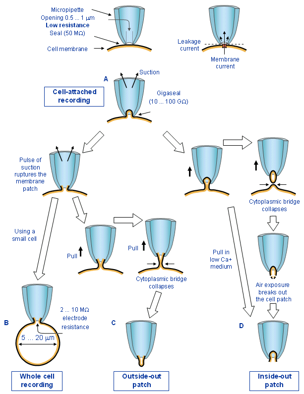
- Fig. 4.27. Schematic illustration of the four different methods of patch clamp:
(A) cell-attached recording,
(B) whole cell configuration,
(C) outside-out configuration, and
(D) inside-out configuration.
(Modified from Hamill et al., 1981.)
 If a heat-polished glass microelectrode, called a micropipette, having an opening of about 0.5-1 µm, is brought into close contact with an enzymatically cleaned cell membrane, it forms a seal on the order of 50 MW . Even though this impedance is quite high, within the dimensions of the micropipette the seal is too loose, and the current flowing through the micropipette includes leakage currents which enter around the seal (i.e., which do not flow across the membrane) and which therefore mask the desired (and very small) ion-channel transmembrane currents.
 If a slight suction is applied to the micropipette, the seal can be improved by a factor of 100-1000. The resistance across the seal is then 10-100 GW ("G" denotes "giga" = 109). This tight seal, called gigaseal, reduces the leakage currents to the point where it becomes possible to measure the desired signal - the ionic currents through the membrane within the area of the micropipette.
Cell-attached recording
In the basic form of cell-attached recording, the micropipette is brought into contact with the cell membrane, and a tight seal is formed by suction with the periphery of the micropipette orifice, as described above. Suction is normally released once the seal has formed, but all micropipette current has been eliminated except that flowing across the delineated membrane patch. As a consequence, the exchange of ions between the inside of the micropipette and the outside can occur only through whatever ion channels lie in the membrane fragment. In view of the small size, only a very few channels may lie in the patch of membrane under observation. When a single ion channel opens, ions move through the channel; these constitute an electric current, since ions are charged particles.Whole cell recording
In the whole cell recording, the cell membrane within the micropipette in the cell-attached configuration is ruptured with a brief pulse of suction. Now the micropipette becomes directly connected to the inside of the cell while the gigaseal is maintained; hence it excludes leakage currents. In contrast, the electric resistance is in the range of 2-10 MW . In this situation the microelectrode measures the current due to the ion channels of the whole cell. While the gigaseal is preserved, this situation is very similar to a conventional microelectrode penetration. The technique is particularly applicable to small cells in the size range of 5-20 µm in diameter, and yields good recordings in cells as small as red blood cells.Outside-out configuration
The outside-out configuration is a microversion of the whole cell configuration. In this method, after the cell membrane is ruptured with a pulse of suction, the micropipette is pulled away from the cell. During withdrawal, a cytoplasmic bridge surrounded by membrane is first pulled from the cell. This bridge becomes more and more narrow as the separation between pipette and cell increases, until it collapses, leaving behind an intact cell and a small piece of membrane, which is isolated and attached to the end of the micropipette. The result is an attached membrane "patch" in which the former cell exterior is on the outside and the former cell interior faces the inside of the micropipette. With this method the outside of the cell membrane may be exposed to different bathing solutions; therefore, it may be used to investigate the behavior of single ion channels activated by extracellular receptors.Inside-out configuration
In the inside-out configuration the micropipette is pulled from the cell-attached situation without rupturing the membrane with a suction pulse. As in the outside-out method, during withdrawal, a cytoplasmic bridge surrounded by the membrane is pulled out from the cell. This bridge becomes more and more narrow and finally collapses, forming a closed structure inside the pipette. This vesicle is not suitable for electric measurements. The part of the membrane outside the pipette may, however, be broken with a short exposure to air, and thus the cytoplasmic side of the membrane becomes open to the outside (just the reverse of the outside-out configuration). Inside-out patches can also be obtained directly without air exposure if the withdrawal is performed in Ca-free medium. With this configuration, by changing the ionic concentrations in the bathing solution, one can examine the effect of a quick change in concentration on the cytoplasmic side of the membrane. It can therefore be used to investigate the cytoplasmic regulation of ion channels..Formation of an outside-out or inside-out patch may involve major structural rearrangements of the membrane. The effects of isolation on channel properties have been determined in some cases. It is surprising how minor these artifacts of preparation are for most of the channel types of cell membranes.
4.5.3 Applications of the patch clamp method
From the four patch clamp techniques, the cell-attached configuration disturbs least the structure and environment of the cell membrane. This method provides a current resolution several orders of magnitude larger than previous current measurement methods. The membrane voltage can be changed without intracellular microelectrodes, and both transmitter- and voltage-activated channels can be studied in their normal ionic environment. Figure 4.28 shows recording of the electric current of a single ion channel at the neuromuscular endplate of frog muscle fiber. In the whole cell configuration a conductive pathway of very low resistance as (i.e.,2-10 MW) is formed between the micropipette and the interior of the cell. When the whole-cell configuration is utilized with large cells, it allows the researcher to measure membrane voltage and current, just as conventional microelectrode methods do. But when it is applied to very small cells, it provides, in addition, the conditions under which high-quality voltage clamp measurements can be made. Voltage clamp recordings may be accomplished with the whole cell method for cells as small as red blood cells. Many other cell types could be studied for the first time under voltage clamp conditions in this way. Among them are bovine chromaffin cells, sinoatrial node cells isolated from rabbit heart, pancreatic islet cells, cultured neonatal heart cells, and ciliary ganglion cells.
 A chromaffin cell of 10 µm in diameter can serve to illustrate the electric parameters that may be encountered. This cell has a resting-state input resistance of several giga-ohms (GW) and active currents of about a few hundred picoamperes (pA). If the electrode has a series resistance RS of about 5 MW, that represents a negligible series resistance in the measurement configuration. The membrane capacitance Cm is about 5 pF and thus the time constant tm = RS·Cm is about 25 µs. Thus a voltage clamp measurement may be performed simply by applying a voltage to the micropipette and measuring the current in the conventional way.
 The outside-out configuration is particularly well suited to those experiments where one wants to examine the ionic channels controlled by externally located receptors. The extracellular solution can be changed easily, allowing testing of effects of different transmitter substances or permeating ions. This configuration has been used to measure the dependence of conductance states of the AChR channel in embryonic cells on the permeating ion. The outside-out patches have also been used to isolate transmitter-gated Cl-channels in the soma membrane of spinal cord neurones, in Aplysia neurones, and in the muscle membrane of Ascaris.
 The inside-out configuration is suitable for experiments where the effects of the intracellular components of the ionic channels are under study. Such control over the composition of solutions on both sides of a membrane has been possible, in the past, only with quite involved techniques. Patch clamp methods with the inside-out configuration is a simple way to achieve this goal. Most of the studies to date have involved the role of intracellular Ca2+. This configuration has also been used for permeability studies, and for exposing the inner surface of electrically excitable membranes to agents that remove Na+ channel inactivation.
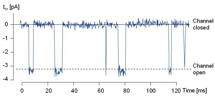
Fig. 4.28. Registration of the flow of current through a single ion channel at the neuromuscular endplate of frog muscle fiber with patch clamp method. (From Sakmann and Neher, 1984.)
4.6 MODERN UNDERSTANDING OF THE IONIC CHANNELS
4.6.1 Introduction
Although the Hodgkin-Huxley formalism was published over 40 years ago, in many ways, it continues to be satisfactory in its quantitative predictability and its conceptual structure. Still the Hodgkin-Huxley equations are empirically derived from a series of carefully devised experiments to measure total and component membrane ionic currents of the squid axon. To obtain the desired data on these currents, space and voltage clamping were introduced. The voltage clamp eliminated capacitive currents, whereas the space clamp eliminated otherwise confounding axial current flow. The measured quantity was the total current of a macroscopic membrane patch which, when divided by the membrane area, gave the ionic current density. Since the result is an integrated quantity, it leaves open the behavior of discrete membrane elements that contribute to the total. Hodgkin and Huxley were aware that the membrane was primarily lipid with a dielectric constant in the neighborhood of 5 and an electric resistivity of 2×10⁹ Wcm, an obviously excellent insulator. Two leading hypotheses were advanced to explain ion currents through such a medium, namely carrier-mediated transport and flow through pores (or channels). Hodgkin and Huxley did not distinguish between these two possibilities, though in their final paper (Hodgkin and Huxley, 1952d, p. 502) they did note that the most straightforward form of the carrier hypothesis was inconsistent with their observations.
 At this time, researchers have studied membrane proteins with sufficient care to know that they are much too large to catalyze ion fluxes known to exceed 106 ions per "channel" per second. Although these proteins have been investigated by a number of techniques their structure is still not definitively established; nevertheless, many features, including the presence of aqueous channels, are reasonably well understood. In the remainder of this section we describe some of the details of structure and function. Our treatment here is necessarily brief and only introductory; the interested reader will find extensive material in Hille (1992).
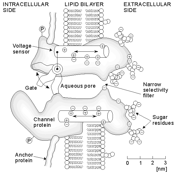
Fig. 4.29. Working hypothesis for a channel. The channel is drawn as a transmembrane macromolecule with a hole through the center. The functional regions - namely selectivity filter, gate, and sensor - are deducted from voltage clamp experiments and are only beginning to be charted by structural studies. (Redrawn from Hille, 1992.)
 Before proceeding it is useful to introduce a general description of a channel protein (illustrated in Figure 4.29). Although based on recognized channel features, the figure is nevertheless only a "working hypothesis." It contains in cartoon form the important electrophysiological properties associated with "selectivity" and "gating", which will be discussed shortly. The overall size of the protein is about 8 nm in diameter and 12 nm in length (representing 1800-4000 amino acids arranged in one or several polypeptide chains); its length substantially exceeds the lipid bilayer thickness so that only a small part of the molecule lies within the membrane. Of particular importance to researchers is the capacity to distinguish protein structures that lie within the membrane (i.e., hydrophobic elements) from those lying outside (i.e., hydrophilic extracellular and cytoplasmic elements). We have seen that membrane voltages are on the order of 0.1 V; these give rise to transmembrane electric fields on the order of 106 V/m. Fields of this intensity can exert large forces on charged residues within the membrane protein, as Figure 4.29 suggests, and also cause the conformational changes associated with transmembrane depolarization (the alteration in shape changes the conductance of the aqueous pore). In addition, ionic flow through aqueous channels, may be affected by fixed charges along the pore surface.
4.6.2 Single-channel behavior
As noted previously, it is currently believed that membrane proteins that support ion flux contain water-filled pores or channels through which ion flow is assumed to take place. The application of patch-clamp techniques has made it possible to observe the behavior of a single channel. In that regard, such studies have suggested that these channels have only two states: either fully open or fully closed. (Measurements such as those performed by Hodgkin-Huxley can thus be interpreted as arising from the space-average behavior of a very large number of individual channels). In fact, most channels can actually exist in three states that may be described functionally as
 | Resting  Open Open  Inactivated Inactivated |
An example is the sodium channel, mentioned earlier in this chapter. At the single-channel level, a transthreshold change in transmembrane potential increases the probability that a resting (closed) channel will open. After a time following the opening of a channel, it can again close as a result of a new channel process - that of inactivation. Although inactivation of the squid axon potassium channel was not observed on the time scale investigated, new information on single channels is being obtained from the shaker potassium channel from Drosophila melanogaster which obeys the more general scheme described above (and to which we return below). In fact, this preparation has been used to investigate the mechanism of inactivation. Thus a relative good picture has emerged.
4.6.3 The ionic channel
There are many types of channels, but all have two important properties in common: gating and selective permeability. Gating refers to the opening and closing of the channel, depending on the presence of external "forces." Channels fall into two main classes: (1) ligand-gated channels, regulating flux of neurotransmitters (e.g., the acetylcholine-sensitive channel at the neuromuscular junction); and (2) voltage-gated channels, which respond to electrolytes (e.g., sodium, potassium, and calcium). The second feature, selective permeability, describes the ability of a channel to permit flow of only a single ion type (or perhaps a family of ions). Neurotoxins that can block specific channel types are important tool in the study of membrane proteins. The first neurotoxin used in this way was tetrodotoxin (TTX) (see Section 4.3.3), a highly selective and powerful inhibitor of sodium channel conductance. Since TTX can eliminate (inactivate) sodium currents selectively from the total ionic current, it can be useful in studies attempting to identify the individual ionic membrane current components. The fact that TTX eliminates sodium flux exclusively also lends support to the idea that sodium ions pass only through specific sodium channels. By using a saturating amount of a radioactively labeled toxin; one can evaluate the target channel density. (For sodium, the channel density is quite sparse: 5-500 per µm² of membrane.) These labeled toxins are useful also in purifying channel preparations, making possible structural studies.
 We now describe briefly three types of techniques useful for elucidating channel structure: (1) biophysical, (2) molecular biological and (3) electron microscopical and electron diffraction. Although a fairly consistent picture emerges, much remains speculative, and an accurate picture of channel structure remains to emerge.
4.6.4 Channel structure: biophysical studies
The Hodgkin-Huxley equations provide excellent simulations under a variety of conditions; these equations have been discussed in the earlier sections of this chapter and are summarized in Sections 4.4.3 and 4.4.4. Hodgkin and Huxley considered the physical implications of the results obtained with these equations. Thus the variables m, n, and h, rather than being considered abstract parameters, were thought to reflect actual physical quantities and were therefore interpreted to describe charged particles in the membrane that would be found at either the inner or outer surface and were required to open or close membrane "channels." This literal interpretation of the Hodgkin-Huxley equations is presented earlier in this chapter. Hodgkin and Huxley however, were aware of the limitations of such speculations (Hodgkin and Huxley, 1952d): "Certain features of our equations are capable of physical interpretation, but the success of our equation is no evidence in favor of the mechanism of permeability change we tentatively had in mind when formulating them." More definitive studies, including true single channel recordings, are now available. Figures 4.30 and 4.31 show single-channel recordings obtained in response to a voltage clamp; Figure 4.30 indicates the response of a sodium channel to a depolarization of 40 mV; whereas Figure 4.31 shows the response of a squid axon potassium channel to a change in voltage from -100 mV to 50 mV. If one disregards the noise, then clearly the channel is either in a conducting or nonconducting condition. (In fact, although the transitions are obviously stochastic, careful study shows that the openings and closings themselves are sudden in all situations). The average of 40 sequential trials, given at the bottom of Figure 4.30, can be interpreted also as the total current from 40 simultaneous sodium channels (assuming statistically independent channel behavior). The latter approaches what would be measured in an Hodgkin-Huxley procedure where a large number of channels would be simultaneously measured. The same observations apply to the potassium channels illustrated in Figure 4.31. The averages shown bear a striking resemblance to Hodgkin-Huxley voltage clamp data.
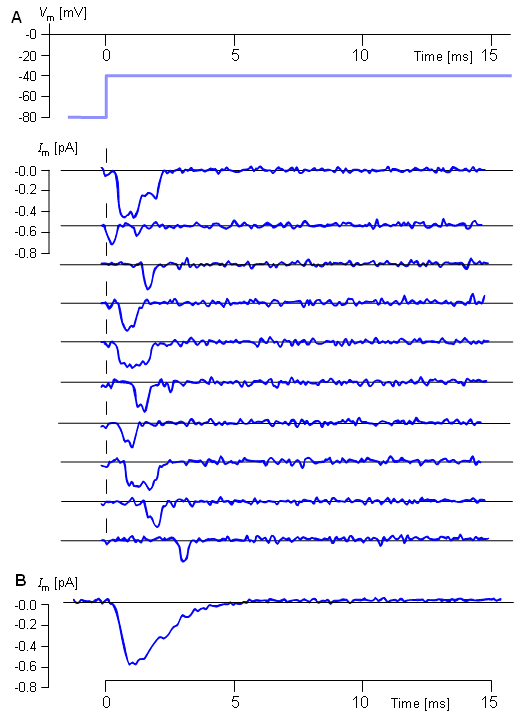
Fig. 4.30. Gating in single sodium channels: Patch clamp recording of unitary Na currents in a toe muscle of adult mouse during a voltage step from -80 to -40 mV. Cell-attached recording from a Cs-depolarized fiber.
(A) Ten consecutive trials filtered at 3-KHz bandwidth. Two simultaneous channel openings have occurred in the first record; the patch may contain over 10 sodium channels. The dashed line indicates the current level when channels are all closed (background current).
(B) The ensemble mean of 352 repetitions of the same protocol. T = 15 °C. (From Hille, 1992, as provided by J. B. Patlak; see also Patlak and Ortiz, 1986.).
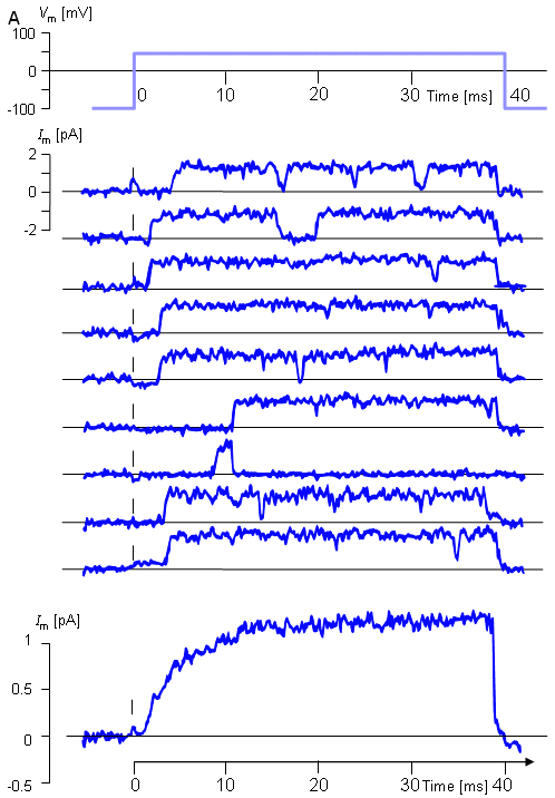
Fig. 4.31. Gating in single potassium channels: Patch clamp recording of unitary K currents in a squid giant axon during a voltage step from -100 to +50 mV.
(A) Nine consecutive trials showing channels of 20-pS conductance filtered at 2-KHz bandwidth.
(B) Ensemble mean of 40 trials. T = 20 °C. (From Hille, 1992, based on data from Bezanilla F and Augustine CK, 1986.).
 The single-channel behavior illustrated in Figure 4.31 demonstrates the stochastic nature of single-channel openings and closings. Consistent with the Hodgkin-Huxley model is the view that this potassium channel has the probability n4 of being open. As a result, if GK max is the conductance when all of the channels are open, then the conductance under other conditions GK = GK max·n4 And, of course, this is precisely what the Hodgkin-Huxley equation (4.13) states.
 One can interpret n as reflecting two probabilities: (1) that a subunit of the potassium channel is open, and (2) that there are four such subunits, each of which must be in the open condition for the channel itself to be open. Hodgkin and Huxley gave these probabilities specific form by suggesting the existence of gating particles as one possible physical model. Such particles have never been identified as such; however, the channel proteins are known to contain charged "elements" (see Figure 4.29), although in view of their overall electroneutrality, may be more appropriately characterized as dipole elements. The application of a depolarizing field on this dipole distribution causes movement (i.e., conformational changes) capable of opening or closing channel gates. In addition, such dipole movement, in fact, constitutes a capacitive gating current which adds to that associated with the displacement of charges held at the inside/outside of the membrane. If the applied field is increased gradually, a point is finally reached where all dipoles are brought into alignment with the field and the gating current reaches a maximum (saturation) value. In contrast, the current associated with the charge stored at the internal/external membrane surface is not limited and simply increases linearly with the applied transmembrane potential. Because of these different characteristics, measurements at two widely different voltage clamps can be used to separate the two components and reveal the gating currents themselves (Bezanilla, 1986).
4.6.5 Channel structure: studies in molecular genetics
In recent years, gene cloning methods have been used in those investigations of channel structure designed to determine the primary amino acid sequence of channel proteins. One can even test the results by determining whether a cell that does not normally make the protein in question will do so when provided the cloned message or gene. Oocytes of the African toad Xenopus laevis are frequently used to examine the expression of putative channel mRNA. The resulting channels can be patch clamped and their voltage and ligand-gating properties investigated to confirm whether the protein synthesized is indeed the desired channel protein. Although the primary structures of many channels have now been determined, the rules for deducing secondary and tertiary structure are not known. Educated guesses on the folding patterns for a protein chain can be made, however. One approach involves searching for a stretch of 20 or so hydrophobic amino acids since this would most probably extend across the membrane and exhibit the appropriate intramembrane (intralipid) behavior. In this way, the linear amino acid sequence can be converted into a sequence of loops and folds based on the location of those portions of the molecule lying within the membrane, within the cytoplasm, and within the extracellular space. The hydrophobic stretches of the amino acid sequence assigned to the membrane might provide indication of the structure and the boundaries of the ion-conducting (i.e., pore-forming) region, as well as the location of charge groups that might be involved in voltage-sensing gating charge movement.
 This approach was successfully used in the study of shaker potassium ion inactivation. Following activation of this channel, the ensuing inactivation was found to be voltage- independent. One can therefore deduce that the inactivation process must lie outside the membrane; otherwise it would be subjected to the effects of the membrane electric field. For this reason as well as other reasons, the amino-terminal cytoplasmic domain of the membrane protein was investigated by constructing deletion mutants whose channel gating behavior could then be examined. The results demonstrated that inactivation is controlled by 19 amino acids at the amino-terminal cytoplasmic side of the channel and that these constitute a ball and chain (Hoshi, Zagotta, and Aldrich, 1990). What appears to be happening is that associated with channel activation is the movement of negative charge into the cytoplasmic mouth of the channel, which then attracts the positively charged ball; movement of the ball (which exceeds the channel mouth in size) then results in closure of the channel.
 Some hypotheses can be tested by site-directed mutagenesis, by which specific protein segments are deleted or inserted as just illustrated, or other such manipulations are performed (Krueger, 1989). By examining the altered properties of the channel expressed in Xenopus oocytes, one can make educated guesses on the function of certain segments of the protein. Of course, since the changes can have complex effects on the (unknown) tertiary structure, the conclusions must be considered as tentative.
4.6.6 Channel structure: imaging methods
Direct imaging of membrane proteins would, indeed, provide the structural information so greatly desired. X-ray crystallography is used to study macromolecules at atomic resolution, but it can be used only when the molecule is repeated in a regular lattice. It has generally not been possible to crystallize membrane proteins; however, two-dimensional arrays of concentrated purified proteins have been assembled into lipid bilayers with reasonably regular spacing. X-ray diffraction and electron microscopy (EM) have been used in such investigations, and images with modest resolution have been obtained. One example is the EM examination of the Torpedo neuromuscular junction acetylcholine receptor (nAChR) (Toyoshima and Unwin, 1988). The molecule was found to be 8 nm in diameter, with a central well of 2.0 nm. Viewed on face, the protein has a rosette-like appearance with five subunits. The subunits function like barrel staves in delineating the aqueous channel. Unfortunately, the resolution of the image is too large to identify the central pore and its shape with any certainty. It is thought that the central pore is actually nonuniform in diameter and, as described in Figure 4.29, has a narrow part which acts as a selectivity filter. Since the intramembrane subunits appear to be oriented as barrel-staves with the pore resulting from a geometrically defined space, this space will be very sensitive to the tilt of the subunits. A small change in tilt arising from a change in transmembrane potential (i.e., a change in electrostatic force) could thereby quickly switch the channel from open to closed and vice versa. Such a hypothesis is developed by (Zampighi and Simon, 1985).
4.6.7 Ionic conductance based on single-channel conductance
The equivalent electric circuit of the single channel is a resistance in series with a battery and switch. (There is, of course, a parallel capacitance, representing the associated patch of lipid-bilayer dielectric.) The battery represents the Nernst potential of the ion for which the channel is selectively permeable while the switch reflects the possible states discussed above (namely open, closed, and inactivated). Referring to Figure 4.29 from which the aqueous pore dimension of 2.5 nm diameter and 12.0 nm length is suggested, then the ohmic conductance of such a cylinder, assuming a bulk resistivity of 250 cm, is 105 pS a value that lies in the range of those experimentally determined. (Since the channel is of atomic dimensions, the model used here is highly simplified and the numerical result must be viewed as fortuitous. A more detailed consideration of factors that may be involved is found in Hille (1992). Based on this model one determines the channel current to be iK = gK(Vm - VK), where gK is the channel conductivity and VK the Nernst potential (illustrated here for potassium). Under normal conditions the channel conductance is considered to be a constant so that the macroscopic variation in ionic conductance arises from changes in the fraction of open channels (exactly the effect of the gating variables n, m, and h for the squid axon ionic conductances). The statistical behavior of the single channel can be obtained from an examination of the behavior of a large number of identical and independent channels and their subunits (the single subunit being a sample member of an ensemble). If Nc are the number of closed subunits in the ensemble and No the number that are open then assuming first-order rate processes with a the transfer rate coefficient for transitions from a closed to open state while b the rate from open to closed gives the equation
  | (4.34) |
from which one obtains the differential equation
  | (4.35) |
Since the total number of subunits, N, must satisfy N = Nc(t) + No(t), where N is a fixed quantity, then the above equation becomes
  | (4.36) |
Dividing Equation 4.36 through by N and recognizing that n = No/N as the statistical probability that any single subunit is open, we arrive at
  | (4.37) |
which corresponds exactly to Equation 4.12. This serves to link the Hodgkin-Huxley description of a macroscopic membranes with the behavior of a single component channel. Specifically the transfer rate coefficients a and b describe the transition rates from closed to open (and open to closed) states. One can consider the movement of n-particles, introduced by Hodgkin and Huxley, as another way of describing in physical terms the aforementioned rates. (Note that n is a continuous variable and hence "threshold" is not seen in a single channel. Threshold is a feature of macroscopic membranes with, say, potassium, sodium, and leakage channels and describes the condition where the collective behavior of all channel types allows a regenerative process to be initiated which constitutes the upstroke of an action pulse.) In the above the potassium channel probability of being open is, of couse, n4.
 While the description above involved the simultaneous behavior of a large number of equivalent channels, it also describes the statistics associated with the sequential behavior of a single channel (i.e., assuming ergodicity). If a membrane voltage step is applied to the aforementioned ensemble of channels, then the solution to Equation 4.36 is:
  | (4.38) |
It describes an exponential change in the number of open subunits and also describes the exponential rise in probability n for a single subunit. But if there is no change in applied voltage, one would observe only random opening and closings of a single channel. However, according to the fluctuation-dissipation theorem (Kubo, 1966), the same time constants affect these fluctuations as affect the macroscopic changes described in Equation 4.38. Much work has accordingly been directed to the study of membrane noise as a means of experimentally accessing single-channel statistics (DeFelice, 1981)..


